Honeywell D06F Pressure Reducing Valve
Application scope
According to the EN 806-2 standard, this type of pressure reducing valve is used to protect household water facilities from excessive water supply pressure, and can also be used for industrial or commercial applications within its specification range. Installing a pressure reducing valve can avoid pressure damage, reduce water consumption, maintain a constant set pressure (even if the inlet pressure fluctuates greatly), and reduce flow noise in the facility.
Authentication
DVGW certification
WRAS certification (temperature not exceeding 23 ° C)
Compliant with BS EN 1567 standard
All materials are certified by UBA, ACS, and SWRAS
Special Features
The inlet pressure is balanced, and the fluctuation of inlet pressure does not affect the outlet pressure
Products with a size of 1 ¼ “are LGA certified, low-noise, belong to Group 1, and have no restrictions
The valve core is made of high-quality synthetic materials and can be completely replaced
Set the water outlet pressure by rotating the adjustment knob, and the set pressure is directly displayed on the set point scale
Adjust the spring to avoid contact with drinking water
Built in fine filter
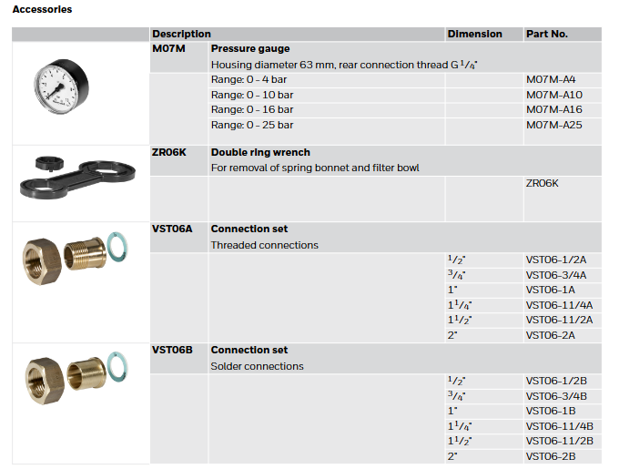
A version without accessories can also be provided
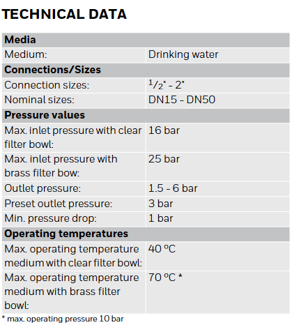
Technical data
Medium: drinking water
Connection/Size:
Connection size: 1/2 “-2”
Nominal size: DN15- DN50
Pressure value:
Maximum inlet pressure with transparent filter bowl: 16 bar
Maximum inlet pressure with brass filter bowl: 25 bar
Outlet pressure: 1.5-6 bar
Preset outlet pressure: 3 bar
Minimum pressure drop: 1 bar
Working temperature:
Maximum working temperature of media with transparent filter bowl: 40 ° C
Maximum working temperature of medium with brass filter bowl: 70 ° C (* maximum working pressure 10 bar)
Note: If the valve may be exposed to ultraviolet radiation or solvent vapors, please use an SM06T brass filter bowl.
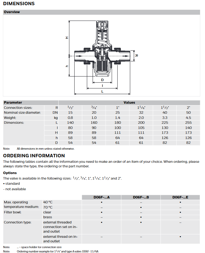
Structure
Overview of Component Materials
-High quality synthetic material for spring valve cover with adjustment knob and setting scale
-Valve body with pressure gauge interface on both sides made of anti zinc brass
-External thread connection (options A and B) brass
-Pressure gauge interface-
-Filter bowl made of transparent synthetic material or brass
-Adjust the spring steel of the spring
-Complete valve core with diaphragm and seat, high-quality synthetic material, EPDM diaphragm
-Stainless steel fine filter with 0.16 mm mesh
-Pressure gauge (see attachment) made of high-quality synthetic materials
-Sealing element EPDM
Working principle
The spring-loaded pressure reducing valve operates through a force balancing system. The force of the diaphragm opposes the force of the regulating spring. When the outflow pressure decreases due to water intake (resulting in a decrease in diaphragm force), the greater force of the spring will open the valve, causing the outflow pressure to increase until the force between the diaphragm and the spring is balanced again. The inlet pressure has no effect on the opening or closing of the valve, so fluctuations in inlet pressure will not affect the outlet pressure, thus achieving inlet pressure balance.
Transportation and Storage
The parts should be kept in their original packaging and opened before use. The following parameters should be followed during transportation and storage:
Environment: clean, dry, dust-free
Minimum ambient temperature: 5 ° C
Maximum ambient temperature: 55 ° C
Minimum relative humidity: 25% (non condensing)
Maximum relative humidity of the environment: 85% (non condensing)
Installation guide
INSTALLATION REQUIREMENTS
Installed in a horizontal pipeline with the filter bowl facing downwards
Install globe valve
Downstream equipment should be protected by a safety valve (installed downstream of the pressure reducing valve), and the output pressure of the pressure reducing valve should be set to be at least 20% lower than the response pressure of the pressure relief valve according to EN 806-2 standard
The installation location should be antifreeze and easily accessible
The pressure gauge should be easy to read
Equipped with a transparent filter bowl, it is easy to check the degree of pollution
Easy to maintain and clean
Installed downstream of the filter or mesh
Provide a straight pipe section at least five times the nominal size of the valve after the pressure reducing valve (in accordance with EN 806-2 standard)
Regular maintenance is required according to EN 806-5 standard
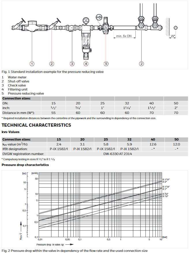
Installation Example
Standard installation examples include water meters, globe valves, check valves, filter units, pressure reducing valves, etc. Valves of different nominal sizes have corresponding installation distance requirements.