GE MII series modular microcomputer relay
Product Overview
Core positioning
The MII series is a modular microcomputer relay designed specifically for digital relay protection applications, characterized by economy and practicality, suitable for the protection and control of various power system equipment, such as feeders, small generators, motors, transformers, etc.
Main advantages
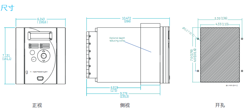
Usability: Unified front panel programming interface and standard hole size, easy to install and operate; Support configuration through the front panel keypad or EnerVista software.
Flexibility: Function configuration can be selected according to actual needs (such as event reporting, waveform capture, circuit breaker failure protection, etc.), equipped with programmable logic and I/O interfaces.
Scalability: Adopting flash technology, supporting on-site firmware upgrades, keeping up with technological developments.
Convenient maintenance: Equipped with event recording and waveform capture functions, it shortens troubleshooting time and reduces maintenance costs.
Core functions and features
1. Protection function
Covering various protective components, different models (MIF II, MIG II, MIN II, MIV II, MIW II, MIB II) support different functions with emphasis, mainly including:
Current protection: phase/ground instantaneous overcurrent (50PH/50PL, 50NH/50NL), phase/ground delayed overcurrent (51P, 51N), current imbalance (46), etc.
Voltage protection: phase undervoltage (27P), phase/ground overvoltage (59N, 59N), voltage imbalance (47), etc.
Power and frequency protection: reverse power (32RP), forward low power (32LF), demagnetization (40), over/under frequency (81O, 81U), etc.
Special protection: differential protection (87), restrictive grounding fault (87R), circuit breaker failure protection, fuse failure (VTFF), etc.
Support multiple fixed value setting groups (2 independent fixed values that can be switched in multiple ways) to meet the needs of different operating scenarios.
2. Monitoring and measurement
Measurement parameters: phase/ground current, voltage, frequency, thermal imaging, etc., measurement error ≤ ± 3%.
Event recording: Store up to 32 events (with millisecond level time tags), including changes in status such as actions, trips, alarms, etc.
Waveform capture: optional function, sampling 8 times per cycle, storing up to 32 cycles of waveform, can be triggered by internal or external signals for fault diagnosis.
Self check diagnosis: Continuously running after power on, triggering an alarm and recording events when abnormalities are detected.
3. Control and Configuration
Programmable logic: Implement four programmable schemes through four logic gates and timers, and output controllable contacts or panel LEDs.
I/O configuration: 2 configurable contact inputs, 4 configurable contact outputs (lockable), and fixed trip and operation contacts.
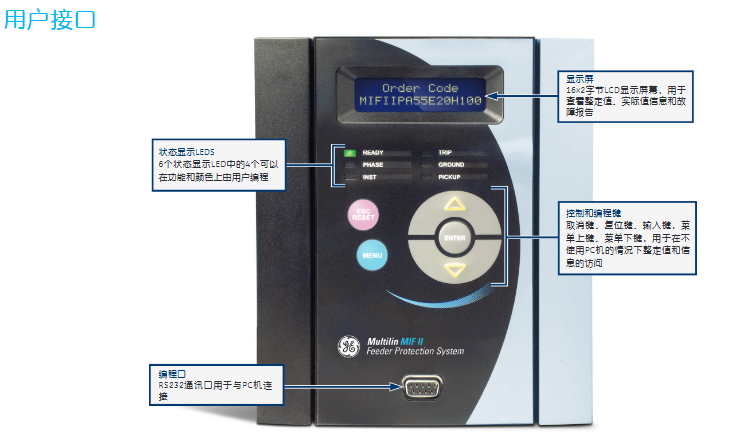
Human machine interface: 2 × 16 character LCD display screen (for viewing fixed values, measured values, and fault reports), 6 LED indicator lights (4 customizable functions and colors), and a 5-key keypad (for local operation).
4. Communication function
Interface: Front panel RS232 interface (local communication), rear RS485 interface (remote communication), supports ModBus ® RTU protocol, with a maximum baud rate of 19200 bps.
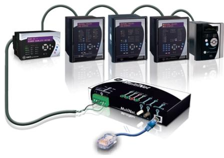
Extended Communication: Compatible with MultiNet modules, capable of converting serial communication to Ethernet ModBus TCP/IP, enabling connection to local/wide area networks, supporting up to 32 devices.
Protection function parameters
1. Current protection
Phase delay overcurrent (51P): Within the time limit of 10-240% of the CT rated value (0-99.99s, with a step difference of 10ms), the inverse time limit and other levels are ± 3%, and the time error is>± 3% or ± 25ms
Grounding delay overcurrent (51N): 10-240% of CT rated value in-phase delay overcurrent in-phase delay overcurrent
Instantaneous overcurrent (50PH/PL): 10-3000% of CT rated value, timed limit (0-99.99s, step difference 10ms), horizontal ± 3%, time error>± 3% or ± 25ms
Grounding instantaneous overcurrent (50NH/NL): 10-3000% of CT rated value, same phase instantaneous overcurrent, same phase instantaneous overcurrent
Current imbalance (46): 5-99% I ² t curve (K=1-100) of CT rated value, with a maximum time limit of 99.99 seconds and a horizontal ± 3% error, and a time error of>± 3% or ± 25ms
2. Voltage protection
Undervoltage (27P): 2.0-60V or 10-250V (with a difference of 0.1V), timed limit (0-600s, with a difference of 0.01s), horizontal ± 3%, time error>± 3% or ± 25ms
Phase overvoltage (59): 2.0-60V or 10-250V (with a difference of 0.1V), in-phase undervoltage, in-phase undervoltage
Grounding overvoltage (59N): 2.0-60V or 10-250V (with a difference of 0.1V)/in-phase undervoltage, in-phase undervoltage
Voltage imbalance (47): 2.0-60V or 10-250V (with a difference of 0.1V), timed limit (0-600s, with a difference of 0.01s), horizontal ± 3%, time error>± 3% or ± 25ms
3. Power and frequency protection
Reverse power (32RP): 0.01-0.99 × rated MW, delay 0.2-120s (with a step difference of 0.1s), supports online locking (0-5000s)
Demagnetization (40): Circle 1 with a diameter of 2.5-300 Ω, offset of 2.5-150 Ω, trip delay of 0.1-10s, double circle characteristics
Overfrequency (81O): 42.0-67.5Hz (level difference 0.01Hz), delay 0.0-600s (level difference 0.01s), voltage braking threshold 30-250V
Underfrequency (81U): 42.0-67.5Hz (level difference 0.01Hz), same over frequency, same over frequency