GE VMIVME-2232 32 32 channel relay output board
Basic Information
Product Name: VMIVME-2232 32 Channel Relay Output Board with Built in Test (BIT)
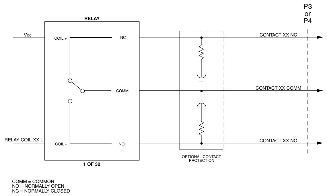
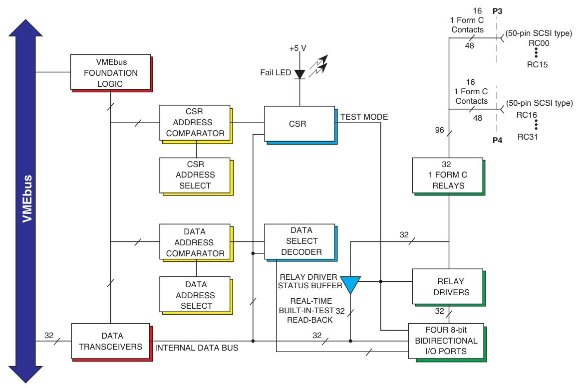
Channel configuration: 32 relay output channels, each channel containing 1 C-type relay
Compatibility: Compatible with the VMEbus specification and has a dual height appearance; Compatible with intelligent I/O controllers; Compatible with VMIVME-2532 and VMIVMME-2533 software
Relay parameters
CONTACT RATING
Maximum switching power: 60W, 125VA
Maximum switch voltage: 220VDC, 250VAC
Maximum switch current: 2A
Maximum carrying current: 3A
UL/CSA certification: 0.6A at 110VDC, 0.6A at 125VAC, 2.0A at 30VDC
Contact life (minimum number of operations)
Mechanical (at 180CPM): 10 times
Electrical: 5 × 10 ⁵ times under 2A 30VDC; 2 x 10 times at 1A 30VDC
Output specifications
Output connector type: SCSI connector, dual 50 pin compatible
Output organization: 4 8-bit wide ports
Built in testing (BIT) function
Test mode activation scenario: software control, onboard power on, after system reset
Test mode features: Relay driver disabled (safety precautions), special test data can be written and read back to test the data path to the relay driver, and the read back data is real data (non inverted)
Non testing mode (online operation)
Positive logic board: When the data bit of the corresponding relay in the data register is set to a specific logic, the relay is activated (normally open contact closed)
Negative logic board: When the data bit of the corresponding relay in the data register is set to a specific logic, the relay is activated
Read back data characteristics: The read back function of the output register is disabled, and the read back data is inverted data
Power on and reset states: configured as test mode, all data registers are in a specific logic state; For negative logic options, data initialization is required before removing the test mode condition, otherwise all relays will be activated
General specifications
Data transmission: Supports 8-bit, 16 bit, or 32-bit data transmission
Address scheme: Four ports can be addressed with 8-bit, 16 bit, or 32-bit boundaries in short I/O addressing, and accessed as corresponding bit width words
Address modifier code: Short monitoring and/or short non privileged I/O access can be selected through jumper, factory configured for short monitoring I/O access
Control and Status Register (CSR): Used to control the front panel fault LED, internal built-in testing functions, and enable/disable relays
Board address: Select jumper in short I/O memory mapping through address selection
Front panel: equipped with a fault LED, which lights up when powered on and can be controlled to turn off through a program
Physical/Environmental Parameters
Temperature: Operating temperature 0-55 ° C; Storage temperature -40-85 ° C
Humidity: 20% -80%, no condensation
Altitude: The working altitude can reach 10000 feet
Cooling method: forced air convection
Power requirement: 3.9A at+5V
Mean Time Between Failures (MTBF): 70540 hours (217F standard)
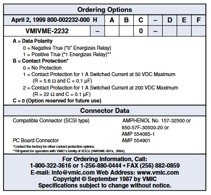
Ordering Options
Data polarity (A): 0 is negative logic (“0” excites the relay); 1 is positive logic (“1” excites the relay)
Contact protection (B): 0 indicates no protection; 1 is a contact protection suitable for 1A switch current, maximum 50VDC (R=5.6 Ω, C=0.1 µ F)
Other options: C=0 is a reserved option for the future; 2 is a contact protection suitable for 1A switch current and maximum 200VDC (R=22 Ω, C=0.1 µ F)
Connectors: The PC board connectors are AMP 554085-1 and AMP 554901