GE VMIVME-2536 32 channel optically coupled digital I/O board
Basic Information
Product Name: VMIVME-2536 32 Channel Optical Coupled Digital I/O Board (with Built in Testing Function)
Production company: GE Fanuc Automation (Embedded Systems Division)
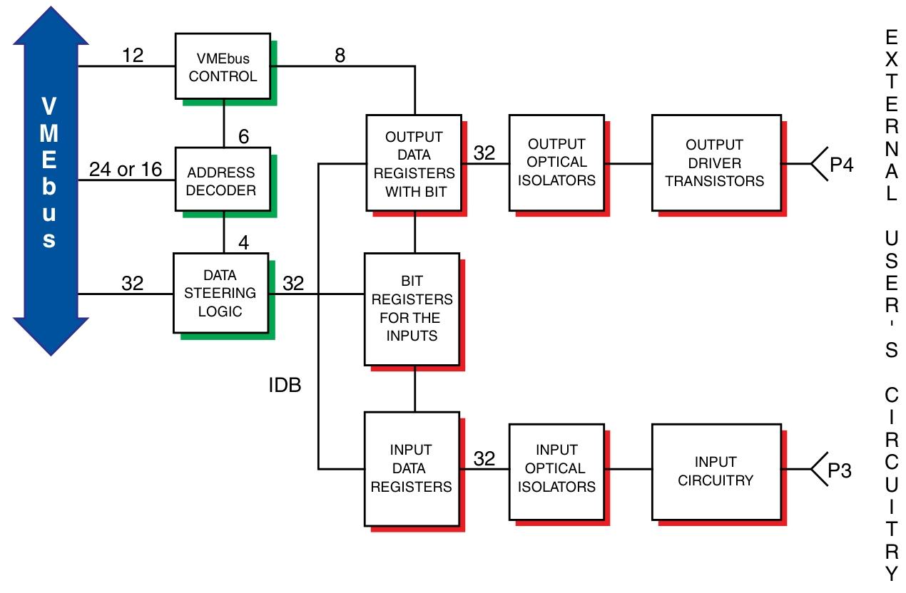
Core function: Includes 32 optically coupled inputs and 32 optically coupled outputs, both with built-in testing (BIT) capability, providing continuous 1kV system isolation for VME backboards
Main features
32 optically coupled outputs and 32 optically coupled inputs
High isolation potential: continuous 1kV, pulse 35kV
Supports 8-bit, 16 bit, and 32-bit data transmission
Supports A24 standard data or A16 short I/O addressing
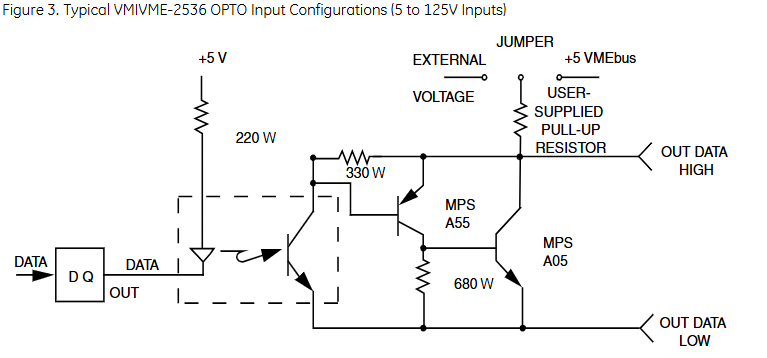
Input can be subjected to voltage induction or contact induction
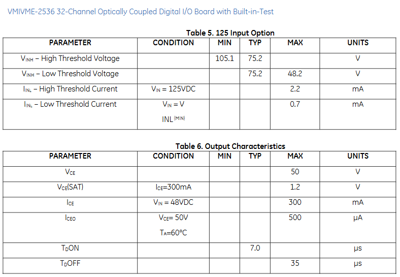
The input voltage range is 5 to 125VDC
Output current up to 300mA, maximum output voltage 50V
Built in testing that supports input and output
Ordering Options
A (input voltage range): 0=5V, 1=12V, 2=24-28V, 3=48V, 4=125V (voltage induction only), 5=reserved
B: 0 (reserved for future options)
C (CE Compliance): 0=Non CE Compliance, 1=CE Compliance
DEF: 0 (reserved for future options)
Functional characteristics
1. Compliance
Compliant with VMEbus specifications ANSI/IEEE STD 1014-1987, IEC 821, and 297
Supported Address Modifiers: 3D, 39/2D, 29
Supports A24/A16 addressing, data transmission supports D32/D16/D08 (EO)
2. Built in testing (BIT)
Input testing: By setting bits in the Control and Status Register (CSR), the input is placed in test mode. At this time, the data read through the input port is from the onboard test register rather than on-site data. The test register has the same address as the input data port and supports both online and offline testing
Output testing: The contents of the output data register can be read at any time to support online testing; By setting the bit in CSR, the output can be placed in offline testing mode, where the open collector output is completely disabled. This allows for testing of data writing and reading modes in the output register without affecting the output
Power on/reset state: The board is in test mode, and the output data register should be initialized before going online to avoid uncertain states
3. Addressing scheme and address mapping
Addressing organization: Organized by 8-bit ports, including 4 input ports and 4 output ports, located on a long word boundary above the board ID and CS registers, occupying 16 bytes of address space
Address Mapping:
$00: BD ID (Board ID)
$02: Control and Status Register (CSR)
$04- $07: Input data register 0-3
$08- $0B: Output data register 0-3
$0C – $0F: Reserved
Input characteristics
Input configuration: can be set as voltage sensing or contact sensing (set according to byte boundaries); Contact sensing requires the installation of SIP resistors provided by the user; Select external voltage or internal VME+5V as contact induction mode power supply through jumper according to byte boundaries (VME+5V is only applicable to 5V input option)
Input voltage options: 5V, 12V, 24V, 28V, 48V, 125V (specific parameters are shown in Table 1-5)
Input isolation: minimum 10M Ω
Isolation voltage: 1000V continuously from the site to VME, 3500V per second; maximum continuous voltage between channels is 500V
Contact debounce: Users can program debounce with debounce times of 0, 0.256, 0.512, 1.024, 2.048, 4.096, 8.192, and 16.384ms. When resetting, debounce is set to 0 by default
Output characteristics
Output configuration: Optical isolation, open collector; Users can install pull-up resistors according to byte boundaries; Select external voltage or internal VME+5V via jumper according to byte boundaries to power the pull-up resistor
Output leakage current: maximum 500uA at VCE=50V, TA=60 ° C
Maximum output voltage: 50V
Switching time: see Table 6
Output isolation: minimum 10M Ω
Isolation voltage: 1000V continuously from the site to VME, 3500V per second; maximum continuous voltage between channels is 500V (note: user provided resistance may limit isolation)
Physical/Environmental Specifications
Size: 6U (4HP) single slot Eurocard shape
Height: 9.2 inches (233.4mm)
Depth: 6.3 inches (160mm)
Thickness: 0.8 inches (20.3mm)
User connectors: Two 64 pin DIN connectors (one for input and one for output)
Temperature: Operating temperature 0 to+60 ° C; Storage temperature -55 to+85 ° C
Humidity: 20% to 80%, no condensation
Power requirement:+5VDC, 2.65A
Mean Time Between Failures (MTBF): 463909 hours
Regulatory certification:
EU (CE mark): Complies with EN55024, EN55022 radiation emission A-level standards, etc
United States: FCC Part 15, Class A
Canada: ICES-003, Grade A