GE Power Management SR489 Generator Management Relay
GE Power Management SR489 Generator Management Relay
Product Overview
GE Power Management SR489 is an economical management relay designed specifically for small and medium-sized generators, integrating multiple functions such as protection, metering, monitoring, and diagnosis. It can adapt to synchronous and asynchronous generators (supporting 25/50/60Hz frequencies), with the core goal of ensuring stable operation of generators and simplifying maintenance.
Input/Output (I/O) Configuration
1. Input module
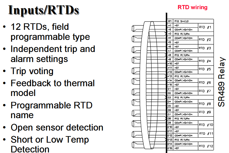
RTD input 12 channel programmable RTD – supports independent trip/alarm settings, trip voting function
-Can provide feedback data to the thermal model, supporting sensor open/short/low temperature detection
-Allow custom RTD names to adapt to different monitoring scenarios such as stators and bearings
9-way digital input (2 pre-defined+7 assignable) – pre-defined functions: access to set values, circuit breaker status (52/a or 52/b)
-Assignable functions: remote reset, test input, hot reset, dual set values, sequential tripping, abnormal excitation circuit breaker, tachometer (closed once per revolution), etc
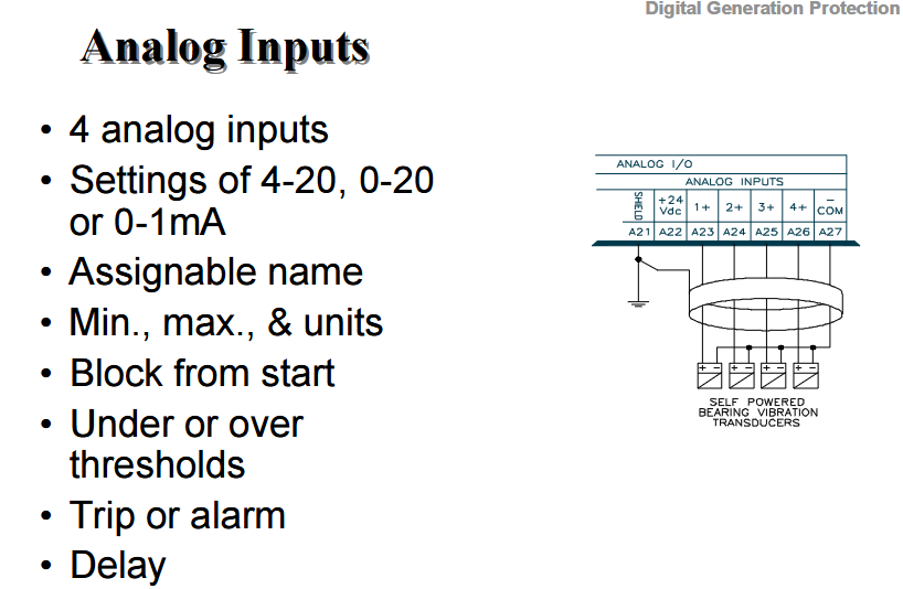
Analog input 4-channel – supports 3 signal types: 4-20mA, 0-20mA, 0-1mA
-Customizable name and unit, set minimum/maximum values, support blocking at startup
-Configurable over/under threshold, triggering trip or alarm (with delay setting)
2. Output module
Output relay 6-way Form C relay – rated load: 10A/30-250V (AC/DC), 30A can maintain for 0.2 seconds
-Used to trigger key control actions such as tripping and alarm
Analog output 4-channel programmable (type to be selected according to order) – optional signal: 4-20mA or 0-1mA
-Supports 29 programmable parameters to meet the external transmission needs of different monitoring data
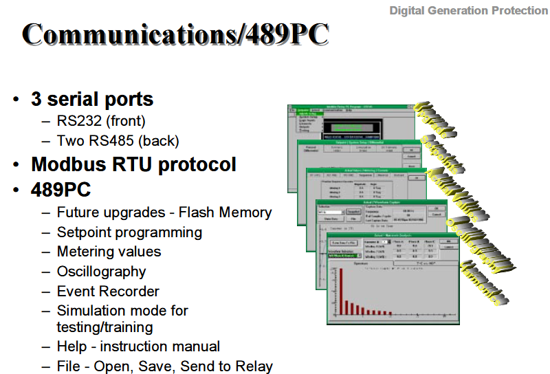
Communication ports: 3 serial ports -1 front RS232 port (convenient for local debugging)
-2 rear RS485 ports (supporting multi device networking)
-Compatible with Modbus RTU protocol, enabling remote data exchange
22 front panel indicator lights and 40 character vacuum fluorescent display screen – the display screen supports 20 optional scrolling messages and customizable text
-Paired with buttons to achieve parameter settings, status viewing, and fault tracing

Generator protection function
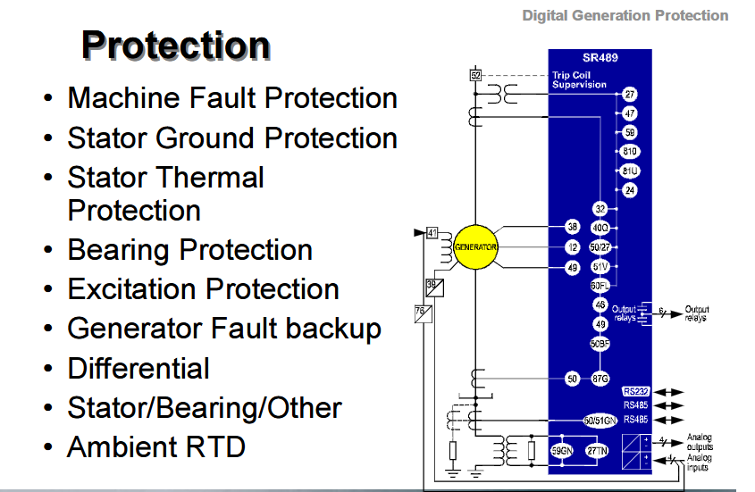
The product covers the full scenario fault protection of generators, which can be divided into the following categories according to the protected objects. Some functions include subdivided technical characteristics:
Unit fault protection differential protection (87G), stator grounding protection (64), grounding overcurrent protection (50/51N), anti electric protection (32) – differential: supports dual slope characteristics
-Stator grounding: dual determination of 95% fundamental overvoltage and 15% third harmonic undervoltage
Thermal and excitation protection stator thermal protection, excitation loss protection (40Q), overexcitation protection (24, based on V/Hz), negative sequence overcurrent protection (46) – overexcitation: prevents iron core overheating through voltage/frequency ratio monitoring
Voltage and Frequency Protection – Undervoltage Protection (27), Overvoltage Protection (59), Underfrequency Protection (81U, 2 groups), Overfrequency Protection (81O, 2 groups), Voltage Phase Sequence Reversal Protection (47) – Voltage/Frequency Protection: Supports curve selection and adapts to different generator withstand characteristics
Special scenario protection starts instantaneous overcurrent (50S), phase overcurrent (51, optional voltage braking), accidental power on protection, circuit breaker fault detection, trip coil monitoring, overspeed protection, VT fuse fault protection – phase overcurrent: can be used as system backup protection to enhance reliability
Temperature and vibration protection, bearing overheating protection, bearing vibration protection, environmental RTD monitoring – based on RTD input and vibration sensor signals, real-time monitoring of equipment health status

Measurement and monitoring functions
1. Electrical parameter measurement (real-time+historical)
Current category: phase current, neutral line current, differential current, negative sequence current, load rate (%), unbalance rate (%);
Voltage and power categories: line voltage (VLN), phase voltage (VLL), active power (MW), reactive power (Mvar), apparent power (MVA), active energy (MWh), positive/negative reactive energy (Mvarh), power factor (PF);
Frequency and demand categories: frequency, current/power (MW/Mvar/MVA) demand (including peak demand), and support for setting demand alarm thresholds.
2. Equipment status monitoring
Physical quantity monitoring: RTD temperature (stator, bearings, etc.), speed (RPM, based on tachometer input), 4-channel analog input signals (such as vibration, pressure, etc.);
Historical data recording: Learn and store the maximum RTD value and the minimum/maximum analog input value for long-term trend analysis.
Maintenance and diagnostic functions
1. Data traceability and statistics
Event recording: Store the last 40 events (with timestamps), recording the number of trips, trip types, startup times, circuit breaker operation times, and operating hours;
Fault data: Retain the last trip data and pre trip data, support waveform capture (16 cycles), and assist in root cause analysis of faults.
2. Self diagnosis and testing
Self testing: Built in self diagnostic function, triggering alarm contacts when abnormal;
Simulation mode: It can be started without external testing equipment, supports pre fault/fault setting, output relay testing, and simulated input testing, simplifying on-site debugging and training.

Physical and Environmental Characteristics
Structural design: with dust-proof door and drawout case for easy installation and maintenance;
Working environment: The temperature and humidity range is not clearly marked, but as an industrial grade relay, it is usually suitable for -20~70 ℃ (operation) and -40~85 ℃ (storage), with humidity ≤ 95% and no condensation (industry standard, subject to official final specifications);
Certification and compatibility: Specific certifications (such as UL, IEC) are not directly mentioned, but they are suitable for general scenarios of small and medium-sized generators and can be compatible with mainstream control systems through Modbus RTU communication.
Order selection parameters (core configuration)
Current input (CT) P1 1A CT input
P5 5A CT input
Control power supply LO 20-60Vdc/20-48Vac
HI 90-300Vdc / 70-265Vac
Analog output A1 0-1mA Analog output
A2 4-20mA analog output


