Yaskawa CP-9200SH Controller
Core positioning and advantages of the product
Positioning: Yaskawa CP-9200SH is a high-end industrial controller that integrates sequential control and motion control, designed specifically for industrial machinery that requires high-speed synchronous operation.
Core advantages:
Modular structure, supporting flexible expansion;
Multi axis control capability, capable of controlling up to 224 axes;
Compatible with multiple communication protocols and I/O modules;
Support hot plugging for easy maintenance;
Equipped with comprehensive debugging and fault diagnosis functions.
Hardware system specifications
(1) Core module types and parameters
Module type, key model, core parameters
Power module PS-01 input: 85-132VAC/90-140VDC, power consumption ≤ 150W
PS-02 input: 170-230VAC, power consumption ≤ 150W
PS-03 input: 19.2-28.8VDC, power consumption ≤ 150W
CPU module CP-9200SH CPU 32-bit processor, program memory 1MB/2MB, supports dual CPU configuration
The SVA motion module can control up to 4 axes and supports position/speed/torque control
PO-01 has a maximum of 4-axis pulse output and supports positioning/zero point return
SVB maximum 14 axis MECHATROLINK control, maximum 224 axis expansion
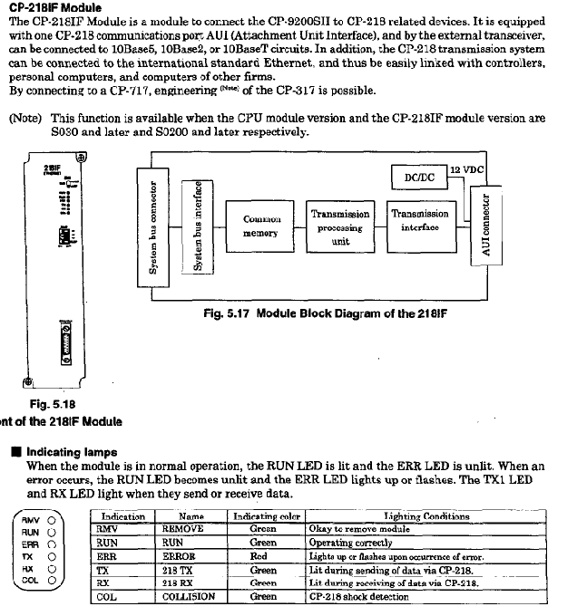
Communication module CP-215IF has a transmission speed of 4Mbps and supports 30 standard sites
CP-217IF supports RS-232/RS-422/485, with a transmission distance of ≤ 300m
I/O module LIO-01 with 32 DI/DO points each
DI-01 DI 64 points
DO-01 DO 64 points
(2) Environmental and Physical Specifications
Working environment: temperature 0-55 ℃ (24-hour average ≤ 50 ℃), relative humidity 5% -95% (no condensation);
Anti vibration: Complies with JIS B 3502, with a half amplitude of 0.075mm at 10-57Hz and an acceleration of 9.8m/s ² at 57-150Hz;
Grounding requirements: protective grounding (Class 3, ≤ 100 Ω);
Installation weight: MB-01 full configuration 5400g, MB-03 full configuration 3400g.
Software and functional features
(1) Program Design
Programming languages: ladder diagram, SFC language;
Programming tool: CP-717 (desktop/laptop);
Program structure: Supports parent, child, and grandson layer level structures, with a maximum of 64 drawings.
(2) Core functions
Control functions: position control, speed control, torque control, electronic cam, electronic shaft synchronization;
Communication function: Supports CP-213/215/216/217/218/225/2500 communication protocol, Ethernet (10Mbps);
Debugging and monitoring: data tracking (up to 4 sets x 16 data, 32k word memory), fault tracking (up to 500 fault definitions);
Special functions: pulse counting, frequency measurement, hardware position locking, hot swapping.
Installation and operation specifications
(1) Installation requirements
Installation location: Avoid direct sunlight, high temperature and humidity, dust, corrosive gases, vibration and impact environments;
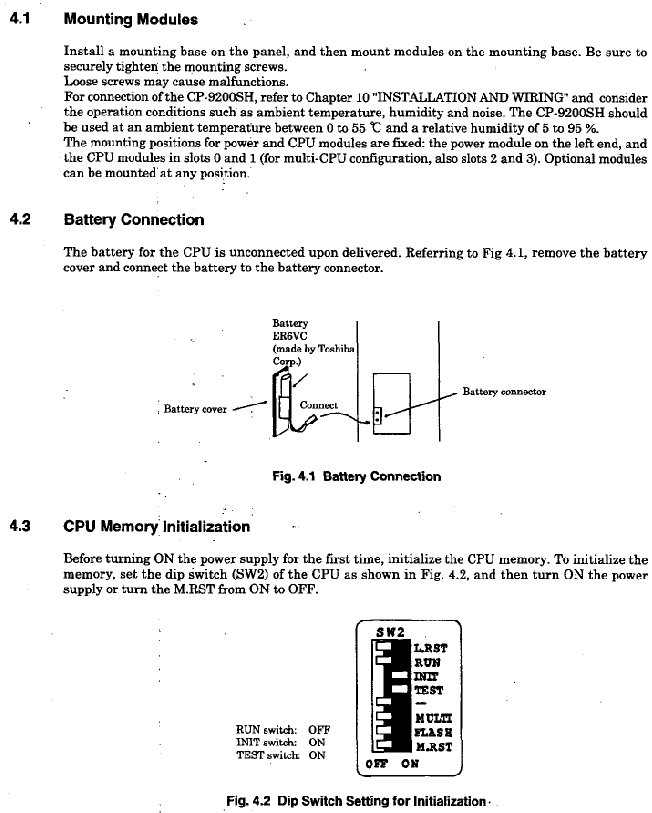
Module installation: The power module is located on the left, the CPU module is in slot 0/1, and the fastening screws are tightened to prevent loosening;
Wiring specification: Separate the power and I/O lines for wiring, with a spacing of ≥ 200mm, to avoid noise interference.
(2) Start and Run
Initiation process: 1 Module installation → 2 Battery connection → 3 CPU memory initialization → 4. Connect CP-717 → 5. Load program → 6 Start running;
Operation mode: online operation mode (executing user programs), offline stop mode (program stops, output reset);
Hot plugging process: Set the BUS switch to HALT → Confirm that the RMV LED is on → Disassemble the module → Install the new module in HALT mode → Tighten the screws → Switch the BUS switch to ACT → Confirm that the RUN LED is on.
Fault handling and maintenance
(1) Fault diagnosis
LED indicator lights: RDY (ready), RUN (running), ALM (alarm), ERR (error), BAT ALM (battery alarm);
System registers: SW00040 (CPU status), SW00041 (error message), SW00200 (I/O error count);
Common faults: power supply error (check voltage range), communication error (check wiring and terminal resistance), program error (check SW00050 error code).
(2) Maintenance points
Battery maintenance: When the BAT ALM light is on, replace the lithium battery (ER6VC) and backup data to prevent loss;
Regular inspection: tighten screws, clean modules, check wiring;
Module replacement: Supports hot swapping, non hot swappable modules need to be powered off for replacement.