YASKAWA S-7 series linear servo
Product basic information
1. Product classification and model
Model system: The core is divided into three categories, corresponding to different iron core structures and application scenarios:
Model Series Structure Type Core Features Applicable Scenarios
SGLG ironless, low inertia, silent operation, precise positioning, high-speed reciprocating motion
SGLF F-type iron core with high thrust density, supporting self cooling/water-cooled medium and heavy-duty automation equipment
SGLT T-shaped iron core vigorously promotes heavy-duty machine tools and large-scale production lines
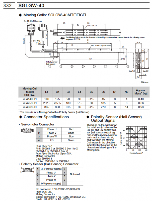
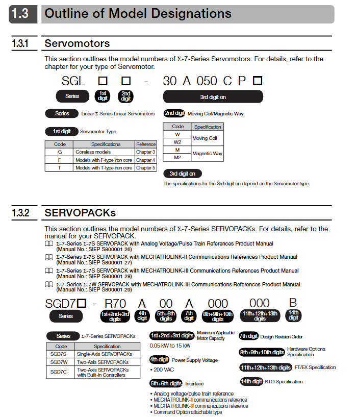
Model interpretation: Taking SGLFW2-30A070AS1 as an example, “SGL” is the ∑ -7 series identifier, “F” is the F-type iron core, “W2” is the rotor, “30” is the magnet height of 30mm, “A” is powered by 200V, “070” is the rotor length of 70mm, “AS” is with polarity sensor and thermal protector, and “1” is the self cooling method.
2. Core performance parameters
Power supply voltage: uniformly 200VAC (single-phase/three-phase), insulation level B, withstand voltage 1500VAC/1 minute
Thrust range: rated thrust 0.1-2520N, instantaneous maximum thrust 30-7560N
Speed range: rated speed 0.5-5m/s, maximum speed 1.5-7.5m/s
Environmental requirements: working temperature 0-40 ℃, humidity 20% -80% RH (non condensing), altitude ≤ 1000m
Selection calculation
1. Core formula for selection
Steady state thrust:F L=9.8×M×(m W+m T+m M)+F(m Acceleration thrust:F P=(m W+m T+m M)× t onev+F L (v is speed, t ₐ is acceleration time)
Effective thrust:F RMS= tF Ptwo⋅t one+F L two⋅t C+F S two⋅t d(t is the cycle time)
2. Selection verification criteria
Acceleration thrust ≤ maximum thrust × 0.9
Effective thrust ≤ rated thrust × 0.9
Load quality ≤ maximum allowable load (to be combined with brake resistor configuration)
Installation specifications
1. Installation environment requirements
Environmental restrictions: Indoor use, no corrosive/explosive gases, no strong magnetic field interference
Mechanical conditions: vibration acceleration ≤ 49m/s ², impact acceleration ≤ 196m/s ² (twice)
Special protection: The magnetic track contains strong permanent magnets and should be kept away from electronic medical equipment such as pacemakers to avoid magnetic substances from approaching
2. Installation operation process
(1) Magnetic track installation
Positioning accuracy: magnetic track spacing tolerance ± 0.1mm, alignment with reference marks when connecting multiple magnetic tracks
Fixed requirement: Use grade 10.9 hex screws with a tightening torque of 3.6-41.5N · m (depending on the model)
Gap control: The gap between the magnetic track and the rotor is 0.8-1.4mm (0.5-1.2mm with magnetic cover)
(2) Assembly of moving parts
Installation steps: First fix the rotor to the workbench → slowly approach the magnetic track → confirm that there is no contact noise → calibrate the gap with a non-magnetic feeler gauge
Screw specification: M4-M8 grade screw, tightening torque 2.4-20N · m, fitting length ≥ 4mm
Cable handling: The moving sub cable needs to be fixed with a bending radius of ≥ 15mm (when the cable diameter is less than 8mm)
3. Special requirements for water-cooled models (SGLFW2-90A series)
Cooling medium: Deionized water, pH6.8-8.0, Conductivity ≤ 30mS/m
Flow pressure: rated flow 4L/min, maximum pressure 0.5MPa, water temperature 5-25 ℃
Protective measures: The pipeline needs to be made of stainless steel material and equipped with a filter (to filter impurities ≥ 0.5mm)
Connection configuration
1. Linear encoder connection
Compatible brands: Supports mainstream brands such as Heidenhain, Renishaw, Mitutoyo, etc
Installation conditions: The distance between the magnetic track and the magnetic track should be ≥ 10-40mm (depending on the motor model) to avoid magnetic leakage interference
Adjustment requirements: The exposed encoder needs to calibrate the position of the scanning head, and the sealed encoder needs to meet the installation tolerance
2. Wiring of servo amplifier
Wiring process: Main circuit cable → Encoder cable → Sensor cable (polarity sensor/thermal protector)
Cable selection:
Recommended models for cable type length restrictions
Servo main circuit cable ≤ 20 meters JZSP-CLN11/21/39 series
Encoder cable ≤ 50 meters JZSP-CLL00/30 series
Sensor cable ≤ 15 meters JZSP-CLL10/CL2L100 series
Grounding requirements: The grounding resistance of the servo amplifier should be ≤ 10 Ω (400V level)/≤ 100 Ω (200V level), and the shielding layer should be grounded at one end
3. Serial Conversion Unit (JZDP Series)
Function: Convert encoder signal to servo amplifier, support polarity sensor and thermal protector signal transmission
Key parameters: Power supply+5V ± 5%, current consumption ≤ 160mA, operating temperature 0-55 ℃
Maintenance and disposal
1. Regular inspection
Daily inspection: Check for vibration, abnormal noise, and cable wear daily to confirm that screws are not loose
Regular inspection: calibrate the gap between the magnetic track and the rotor annually, measure the insulation resistance (≥ 10M Ω/500VDC)
Overhaul cycle: Contact the manufacturer for comprehensive maintenance every 5 years, and do not disassemble on your own
2. Key points for troubleshooting
Common problems: Abnormal encoder signal (check installation spacing), overload alarm (verify effective thrust), cable breakage (check bending radius)
Insulation testing: Measure after disconnecting the servo amplifier, and do not perform voltage withstand testing on the sensor
3. Scrap disposal
Demagnetization requirement: The magnetic track needs to be heated to above 300 ℃ and maintained for 1 hour to eliminate magnetism
Environmental requirements: Follow the WEEE directive and classify the disposal of electronic components and metal casings
Safety and Compliance
1. Core security standards
Strong magnetic protection: The magnetic track has an adsorption force of up to 21500N, and non-magnetic tools should be used during operation to avoid finger squeezing
Power off operation: Disconnect the power before maintenance and wait for the servo amplifier CHARGE indicator light to turn off (≥ 5 minutes)
Static protection: Release static electricity before touching the connector, and do not directly touch the encoder pins with your hands
2. Compliance standards
North America: UL 1004-1, UL 1004-6, CSA C22.2 No.100
EU: CE certification (EMC 2014/30/EU, LVD 2014/35/EU), EN 61800-3
China: RoHS compliance, restricting harmful substances such as lead and mercury