Hirschmann MS20/MS30 series industrial Ethernet switches
Overview
The installation user manual for Hirschmann MS20/MS30 series industrial Ethernet switches (Release 14 03/2023 version) covers four major modules: equipment overview, safety specifications, installation process, basic configuration, maintenance, and technical parameters. It provides detailed instructions on the hardware composition of the equipment (basic module, media module, SFP transceiver, etc.), installation steps (DIN rail installation, wiring, DIP switch configuration), safety compliance requirements (ATEX, IECEx and other hazardous environment certifications), and technical parameters (power supply range of 18-60V DC, working temperature -40 ℃~+70 ℃, port type supporting 10/100/1000Mbit/s twisted pair/fiber ports). It also offers a global technical support channel to provide comprehensive guidance for equipment deployment and operation in industrial scenarios.
Equipment Overview
(1) Product classification and coding
Example of Port Configuration for Core Differences in Equipment Series
MS20 without Gigabit ports, modular design MS20-0800… 8 10/100Mbit/s ports
MS30 includes 2 Gigabit ports, modular design MS30-0802…: 8 10/100Mbit/s+2 1000Mbit/s ports
Product coding rules (15 digits): The first to fourth digits indicate the series (MS20/MS30), the sixth to seventh digits indicate the number of 10/100Mbit/s ports (08/16/24), the tenth digit indicates the temperature range (S: 0~60 ℃, T/E: -40~70 ℃), and the eleventh digit indicates the power supply range (A: 18-32V DC, C/E: 18-60V DC).
(2) Hardware composition
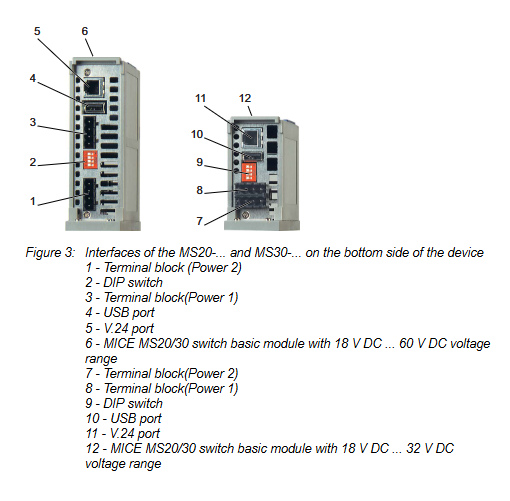
Basic module: including power terminals, DIP switches, USB/V.24 management interfaces, grounding screws, supporting 2 redundant power inputs (P1/P2).
Media module: Supports MM2 (10/100Mbit/s), MM3 (10/100Mbit/s with PTP), MM4 (1000Mbit/s Gigabit), MM22 (PoE port) and other series, with 2-4 ports, supporting twisted pair (RJ45/M12) and fiber optic (ST/LC/DSC) interfaces.
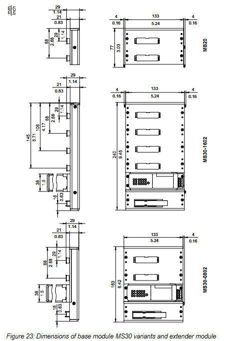
Expansion module: The MB20 expansion module can add 2 media module slots, suitable for MS20-1600/MS30-1602 models.
SFP transceiver: Supports Fast Ethernet/Gigabit Ethernet, including multimode (MM), single-mode (SM), and long haul (LH) types, with a maximum transmission distance of 176km (LH+type).
(3) Port type and function
Port type, speed, interface specifications, core functions
Twisted pair port 10/100/1000Mbit/s RJ45/M12 automatic negotiation, polarity switching AutoCrossing
Fiber optic port 100/1000Mbit/s ST/LC/DSC/MTRJ link monitoring, full duplex mode
PoE port 10/100Mbit/s RJ45 complies with IEEE 802.3af and supports Class 0-3 terminal power supply
AUI port 10Mbit/s Sub-D 15 pin supports SQE testing and DTE power monitoring
Safety regulations
(1) General safety requirements
Anti electric shock: The equipment casing is grounded, and sharp objects are prohibited from contacting the terminals. Only qualified personnel are allowed to operate.
Anti overheating: Keep the ventilation duct unobstructed, reserve a space of ≥ 10cm around the equipment, and avoid touching the casing during operation.
Fireproof: If the power supply does not meet the requirements of Class 2/LPS, it needs to be installed in a metal/flame-retardant plastic shell (V-1 level).
(2) Compliance with hazardous environments
Certification type applicable standard environmental parameters
ATEX EN IEC 60079-0/7/15 Temperature Class T4, Operating Temperature -40~+45 ℃
IECEx IEC 60079-0/7/15 Explosion proof Class II 3G Ex ec nC IIC T4 Gc
Class I Division 2 ANSI/ISA 12.12.01 Groups A-D, ambient temperature -40~+70 ℃
Special requirements: Only temporary connections to USB/V.24 interfaces are allowed in hazardous environments. The connector must be plugged and unplugged in a power-off state, and the signal contact current is limited to 100mA.
(3) Power supply and wiring safety
Power supply requirements: redundant input (P1/P2), DC power supply needs to be grounded to the negative pole, AC power supply needs to be isolated and grounded; Class 2 power supply is required in North America.
Wire specification: Copper wire (75 ℃), terminal supports up to 2.5mm ² (AWG 12) wire.
Shielding grounding: The shielding layer of twisted pair cables needs to be connected to the grounding terminal of the front panel of the equipment to avoid short circuits.
Installation process
(1) Preliminary preparation
Packaging inspection: Confirm the basic module, terminal block (4-pin/6-pin), label, and installation manual are included.
Label filling: Fill in the device name, MAC address, IP address, and other information and paste them on the surface of the device.
(2) Hardware installation steps
Media module/SFP installation: Remove the protective cap, align with the slot, insert and tighten the screws; The SFP transceiver needs to close the latch until it is securely fastened.
DIN rail installation: snap the sliding device onto the rail, press the bottom lock to fix it, and reserve a space of ≥ 10cm up and down.
Grounding: Grounded through DIN rails or dedicated grounding screws, with grounding wire specifications consistent with the power supply wire.
DIP switch configuration:
4-pin DIP switch (MS20/MS30 basic module): controls redundancy manager (RM), ring port selection, standby mode, and configuration priority.
3-pin DIP switch (MS20/MS30-… E…): The function is the same as a 4-pin switch, without a priority switch configured (all three keys are ON for software configuration).
(3) Wiring process
Power wiring: 4-pin terminals (P1/P2:+24V, 0V), 6-pin terminals (MS30-… E…: integrated power and signal contacts).
Signal contact wiring: Potential free relay contacts, supporting up to 1A/60V DC for remote diagnosis.
Data cable connection: Twisted pair cables should use Cat5e or above, and fiber optic cables should be matched with port types (SX/LX/LH) to avoid mixing.
(4) LED display configuration
Display mode switching: Press the “SELECT” button for ≥ 2 seconds to switch the port LED display meaning (link status, duplex mode, rate, etc.).
Device status LEDs: P1/P2 (power), RM (redundant), RUN (running), RL1/RL2 (signal contacts).
Basic configuration and maintenance
(1) Initial configuration
IP configuration method: Supports DHCP/BOOTP, V.24 interface (CLI), AutoConfiguration Adapter, HiView software.
Default account: admin (read-write permission, password private), user (read-only permission, password public). The password needs to be changed for the first login (≥ 8 characters, including uppercase and lowercase letters/numbers/special characters).
Core default settings: RSTP enabled, ring redundancy disabled, port auto negotiation enabled, V.24 baud rate 9600.
(2) Maintenance and disassembly
Daily maintenance: Regularly check relay contact resistance, software updates (downloaded from the official website), and clean ventilation ducts.
Disassembly steps: Disconnect the data cable → Cut off the power supply → Remove the terminal block → Press the guide rail lock to remove the device; SFP disassembly requires opening the latch and pulling it out.
Core technical parameters
(1) Physical and environmental parameters
Specific indicators for parameter categories
Dimensions (W × H × D) MS20-0800:125 × 133 × 100~140mm
Weight 610g (MS20-0800)~1250g (MS30-2402)
Working temperature S-type: 0~60 ℃; T/E type: -40~70 ℃
Storage temperature -40~85 ℃
Protection level IP20
Pollution level 2
(2) Electrical parameters
Specific indicators for parameter categories
Power supply range A: 18-32V DC; C/E type: 18-60V DC
Power consumption MS20-0800: 5.0~7.4W; MS30-2402:12.6~18.0W
Signal contact maximum 1A (≤ 60 ℃)/100mA (60-70 ℃), 60V DC/30V AC
Insulation voltage 800V DC (power terminal and casing)
(3) Port transmission parameters
Port type maximum transmission distance support standard
1000Mbit/s twisted pair 100m IEEE 802.3ab
100Mbit/s multimode fiber (50/125 μ m) 5km IEEE 802.3u
1000Mbit/s single-mode fiber (9/125 μ m) 176km (LH+) IEEE 802.3z
PoE port 100m IEEE 802.3af
Accessories and Support
(1) Optional accessories
Accessory Type Example Model Usage
SFP transceiver M-SFP-LX/LC gigabit single-mode fiber transmission
Power adapter RPS60/48V EEC PoE module power supply
Terminal block 943 845-004 power/signal contact extension (50 pieces)
Configure adapter ACA22-USB local configuration and software updates