YAMAHA RCX40 4-AXIS ROBOT CONTROLLER
Product Overview
Core positioning: A dedicated controller for four axis industrial robots, compatible with SCARA robots and Cartesian robots, focusing on efficient and precise control and compact design.
Core Features
Multi tasking function: Up to 8 tasks can be run simultaneously, supporting priority settings to improve system efficiency.
Programming ability: Equipped with BASIC like high-level language, compatible with industrial robot programming standard SLIM, and using compilation to achieve fast program execution.
Motion control: Supports Arch motion (freely set pick and place paths) and 3D CP control (linear/circular motion interpolation).
Compatibility: Software servo control achieves unit standardization, compatible with most YAMAHA robot models, and simplifies maintenance.
Certification and Compliance: Compliant with CE certification related directives (Machinery Directive, Low Voltage Directive, EMC Directive), operating in SAFE mode by default.
Safety regulations
Security category core requirements risk warning
Warning 1. It is necessary to design a safety interlock circuit and activate the emergency stop terminal;
2. Before installation/wiring, all power phases must be cut off;
3. Prohibited from use in flammable gas environments (non explosion proof design). Violation may result in fatal injury or death
CAUTION 1. The distance between the control line and the power line should be ≥ 100mm to avoid interference;
2. Data needs to be regularly backed up to external storage;
3. Tighten the terminal screws to the specified torque to avoid short circuits;
4. Disposal as industrial waste may result in injury or equipment damage if violated
NOTE 1. Simplified explanation of key operational steps;
2. Some CAUTION items may be upgraded to serious risk auxiliary safety operations in specific environments, and strict compliance is required
Environmental and Protection Requirements
Working temperature: 0-40 ℃ (continuous operation guarantee), storage temperature: -10-65 ℃
Humidity: working environment 35% -85% RH (non condensing), storage environment ≤ 95% RH (non condensing)
Physical protection: IP20 protection level, resistant to conductive dust and corrosive gases
Hardware and interface configuration
Core hardware components
Host: Supports up to 4 axis controls, including POWER/SRV/ERR status indicator lights
Optional devices: MPB handheld programmer (including emergency stop button), expansion I/O board (up to 4 pieces), regeneration unit (configured as needed)
Cable specification: X-CA 011 system cable (LIYCY-TP 18 × 2 × 0.25 mm ²), available in lengths of 8m/15m/30m
Interface details
STD. DIO interface: 10 dedicated inputs, 11 dedicated outputs, 16 universal inputs, 8 universal outputs, supporting NPN/PNP specifications
SAFETY I/O interface: safety related I/O such as emergency stop input, enable switch signal, etc
RS-232C interface: supports data communication with the upper computer, with configurable parameters (baud rate 4800-57600bps, etc.)
Power supply and load specifications
Main power supply: AC200-230V single-phase, allowable voltage fluctuation range -15%~+20%
Load adaptation: resistive load up to 600 Ω, inductive load up to 1mH, capacitive load up to 100 µ F
Operation mode and core functions
Key parameters of core functions in operation mode
AUTO mode program automatic execution, task switching, speed adjustment (1% -100%), breakpoint setting supports PTP/ARCH/LINEAR motion modes
MANUAL mode robot manual movement, point data teaching/editing, absolute reset, coordinate setting manual speed can be adjusted step by step/fine tuning
Program creation/editing/compilation, directory management, user function key registration, maximum 9999 lines per program, storage limit of 100 programs
SYSTEM mode parameter configuration (robot/axis/communication parameters), system initialization, fault diagnosis support data backup to internal Flash ROM
UTILITY mode emergency stop cancellation, motor power switch, execution level setting support access permission hierarchical control
Core function supplement
Data management: supports editing and storage of point data, tray definitions, shift coordinates, and hand definitions, with a point number range of 0-4000
Communication function: RS-232C supports online command execution, data transmission, and supports XON/XOFF or RTS/CTS stream control
Fault diagnosis: supports error history query (up to 500 records), controller self-test, battery voltage monitoring
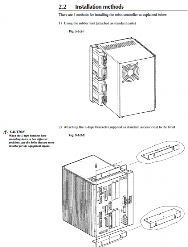
Installation and maintenance
Key installation requirements
Wiring: The distance between the control line and the power line should be ≥ 100mm, and the cable should be threaded or fixed to avoid pulling or pulling
Installation gap: top/side ≥ 50mm, rear ≥ 30mm (to ensure heat dissipation)
Grounding: It must be reliably grounded, and the cross-sectional area of the grounding wire should be ≥ 2.0mm ²
Maintenance cycle and operation
Verification testing: once every 10 years (refer to security manual HI 801 003 E)
Battery replacement: The absolute battery life is about 1.5 years, and it needs to be charged after replacement (B3 battery fully charged for 48 hours, B4 battery fully charged for 96 hours)
Software update: When the system is shut down, load the latest version and the controller needs to be in STOP state
Fault handling
Diagnostic tool: MPB screen error prompt, error history query, self diagnostic function
Common faults: abnormal power supply, communication failure, motor overload, absolute reset failure, etc. Provide corresponding troubleshooting procedures
Compliance and Disposal
Battery disposal: California in the United States has processing restrictions on lithium manganese dioxide batteries and requires compliant disposal
Disposal requirement: When disposing of products, they should be treated as industrial waste
Warranty Statement: The warranty period is 18 months after shipment, 1 year after installation, or 2400 hours of operation (whichever comes first). Natural wear and tear, human modification, and other situations are not covered by the warranty