HIMA X-AO 16 01 HIMax ® Analog Output Module
Core technical specifications
(1) Electrical and output parameters
Category specific specifications
Supply voltage 24 VDC (allowable range: -15%~+20%), SELV/PELV standard
Input current maximum 1.3A, minimum 0.6A (when all outputs are turned off), 80mA per channel
Output channel single channel connection: 16; Redundant connections: 8 (only odd numbered channels AO1, AO3… AO15)
Output range nominal: 4~20 mA; operating: 0~23 mA
Resolution and accuracy 16 bits (10000 digits in SILworX), LSB ≤ 2 µ A; accuracy at 25 ℃ ≤ ± 0.2% full scale, full temperature range ≤ ± 0.5% full scale
Load capacity: maximum resistance of 600 Ω, maximum inductance of 1mH, maximum capacitance of 100 µ F (parallel resistance load)
The response characteristic establishment time is 5ms, and the fault shutdown time is 16ms (in accordance with the principle of “power-off tripping”)
(2) Environmental and physical parameters
Working temperature: 0~+60 ℃, storage temperature: -40~+85 ℃
Humidity: Maximum 95% relative humidity (without condensation)
Protection level: IP20
Dimensions (H × W × D): 310 × 29.2 × 230 mm, weight approximately 1.2kg
Altitude:<2000m, pollution level: Level II (IEC/EN 61131-2)
Hardware composition and connection
(1) Compatible connector board
Model, type, and purpose
X-CB 014 01 single channel, screw terminal single module screw terminal wiring
X-CB 014 02 redundant, screw terminal dual module redundant screw terminal wiring
X-CB 014 03 Single Channel, Cable Plug Single Module Cable Plug Wiring
X-CB 014 04 redundancy, cable plug dual module redundant cable plug wiring
Mechanical coding: The connector board and module are protected against accidental insertion through wedge-shaped coding, and the coding position follows the X-CB 014 series specifications
(2) System cable
Model: X-CA 011 (LIYCY-TP 18 × 2 × 0.25 mm ²)
Length: standard 8m, 15m, 30m, minimum bending radius: fixed installation 5 x cable outer diameter, flexible application 10 x cable outer diameter
Characteristics: Flame retardant and self extinguishing (compliant with IEC 60332-1-2/-2-2), color coding follows DIN 47100
(3) Wiring method
Single channel wiring: Use X-CB 014 01/03 to directly connect the actuator
Redundant wiring (serial): using X-CB 014 02/04, dual modules installed adjacent to each other, sharing actuators
Closed loop control: AO output → actuator → AI input (such as X-AI 32 01) → processor module, forming a feedback loop
FTA connection: Through X-FTA 002 01/X-FTA 009 02, connect the module to the on-site terminal components via system cables
HART communication: The handheld device is connected in parallel at both ends of the actuator, and the residual error after compensating for communication current fluctuations is ≤ 2% of the full range
Configuration and Operation (Based on SILworX Tool)
(1) Core configuration items
Key parameter description for configuring labels
Module Noise Blanking is activated by default, and the processor module delays response to transient faults
Missing modules in the redundant group of Spare Modules are not considered as faults and are automatically shut down by default
I/O submodule AO16_01 Background Test Error: True=Test Fault, False=Normal
I/O submodule AO16_01 Restart on Error Force the faulty module to restart and self check, default shutdown
The default mapping value for Channels 4mA/20mA is 4.0/20.0, and unused channels should be kept as default
After activating Channels redundancy, it is added to the redundancy group and is turned off by default
Channels status (Channel OK): True=Channel normal, False=Channel fault (output set to 0)
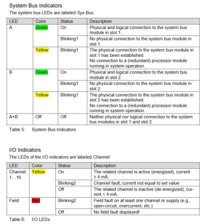
(2) Diagnostic status code
Module Status: 32-bit WORD, such as 0x00000001=module fault, 0x00000010=L1+voltage fault
Submodule Status: For example, 0x00000040=module shutdown due to overcurrent, 0x00000010=temperature threshold 1 overtemperature
Channel diagnosis: supports open circuit detection (OC) and OC Monitoring Defect
Safety and maintenance requirements
(1) Security protection
ESD protection: Only authorized personnel with ESD knowledge are allowed to operate, and must wear anti-static wristbands. Unused modules must be stored in their original packaging
Fault response: In case of module failure, all outputs should be turned off within 16ms; When there is a channel failure, turn off the corresponding channel group (2 channels), and the Error LED will light up
Ex area use: Additional explosion-proof measures need to be taken to avoid sparks caused by plugging and unplugging loaded connectors
(2) Maintenance and disposal
Verification testing: to be conducted every 10 years, refer to the security manual HI 801 003 E
Operating system update: Use system downtime to load the latest version, modules need to be in STOP state
Repair authorization: Only HIMA company has the right to repair, unauthorized intervention will result in safety function failure and warranty failure
Transportation and discontinuation: Original packaging is required for transportation (to prevent ESD and mechanical damage); Discontinuation requires disassembly from the substrate and disposal according to environmental requirements