WOODWARD 2301A Speed Control Controller
Product Overview
Product Name: Woodward 2301A Speed Control Controller
Core positioning: Provide high-precision speed and load control for various types of prime movers (engines, turbines), supporting single operation or parallel load distribution for multiple units
Core advantages:
Dual working modes: equal time mode (maintaining constant speed when load changes), deceleration mode (speed changes with load, adapted for parallel operation)
Wide adaptability: supports forward/reverse actuators, single/dual actuator drivers
High environmental tolerance: working temperature -40 to+85 ° C, anti vibration, electromagnetic interference protection
Safety requirement: An overspeed shutdown device independent of the controller must be equipped, and the use of the minimum fuel contact for emergency shutdown is prohibited
Key technical specifications
(1) Electrical parameters
Category specification remarks
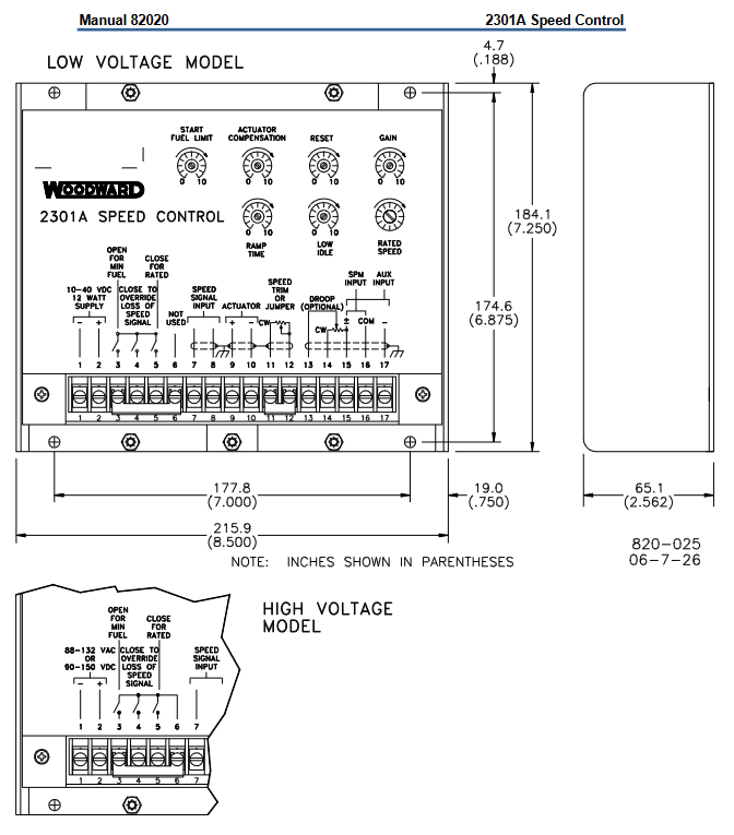
Low input voltage: 10-40Vdc (12W); High voltage: 88-131Vac/90-150Vdc (12W) AC frequency 50-400Hz
Speed sensing magneto electric sensor (MPU), signal range 1.0-30Vrms, minimum starting signal 1.0Vrms (crankshaft speed)
Speed range corresponds to sensor frequency: 500-1500Hz, 1000-3000Hz, 2000-6000Hz, 4000-12000Hz. Internal dip switch selection
Adjustment accuracy speed fine adjustment ± 5% (100 Ω multi turn potentiometer), maximum speed reduction of 8% (2K potentiometer)-
Response characteristic ramp time: 1-22 seconds (idle to rated speed), deceleration ramp<1 second potentiometer adjustment
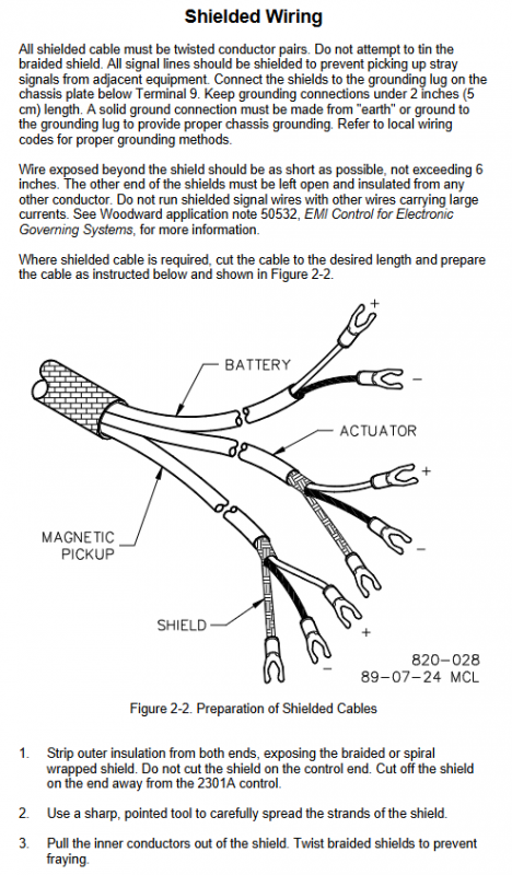
Output terminals 9 (+) and 10 (-) of the actuator support dual series drive (dual actuator) shielded wiring, with the shielding layer only grounded at the controller end
(2) Physical and environmental parameters
Characteristic specification remarks
Dimensions: Low voltage version: 215.9 × 174.6 × 65.1mm; High voltage version: 215.9 × 177.8 × 65.1mm Unit: mm, inches are marked in parentheses
The weight is not clearly marked, and the body material is sheet metal chassis-
Working temperature -40 ° C to+85 ° C No condensation, anti direct water spray
Vibration protection 10-300Hz, 2g acceleration, 30 minutes per axis in accordance with IEC68-2-6 standard
Impact protection: Drop 1 meter into concrete, 1 time on each of the 6 surfaces-
Installation process
(1) Installation preparation
Location selection: Good ventilation, reserved maintenance space, away from high voltage/high current equipment and EMI sources, prohibited from installation on the engine
Power requirements: Low voltage models need to be directly connected to batteries (low impedance), and it is prohibited to draw power from high-voltage sources through resistors/Zener diodes
Shielded wiring: All signal lines use twisted pair shielded cables, with the shielding layer only grounded at the controller end (length<5cm) and exposed wires<15cm
(2) Key wiring
Remarks on Terminal Function Wiring Requirements
Low voltage of power terminal: 1 (+), 2 (-); High voltage: 1 (L), 2 (N) grounding in accordance with local regulations
Sensor terminals 7 and 8 (non-polar) MPU sensor, shield layer connected to the grounding column below terminal 9
Dual actuator terminals 9 (+) and 10 (-) are connected in series
Speed reduction adjustment terminals 13 (wiper), 14 (cw), 15 (ccw) 2K potentiometers, if there is no need for speed reduction, do not wire them
Short circuit the speed adjustment terminals 11 and 12 if there is no need for adjustment
(3) Installation inspection
Visual inspection: The actuator connecting rod is not loose/stuck, the wiring conforms to the drawing, and the terminals are not damaged
Grounding check: The resistance between terminals 7-17 and the grounding column is infinite (except for power terminals that allow grounding)
Sensor inspection: The clearance between MPU and gear meets the requirements, and the signal is ≥ 1.0Vrms when the crankshaft rotates
Operation and adjustment
(1) Pre start settings
Parameter setting value remarks
Minimum rated speed (counterclockwise to the bottom) 10 turn potentiometer
Reset the middle position single turn potentiometer
Gain (GAIN) middle position single turn potentiometer, adjusting too quickly may cause speed fluctuations
Minimum slope time (counterclockwise rotation to the end) to avoid excessive torque
Minimum idle speed (counterclockwise to the bottom) single turn potentiometer
Maximum fuel limit for startup (clockwise needle rotation to the bottom). It is recommended to disable this function for the reverse actuator
(2) Key adjustment steps
Stable operation adjustment: If there is a fast fluctuation, the gain will be reduced; if there is a slow fluctuation, the reset will be increased. If it is still unstable, the actuator compensation can be adjusted
Dynamic adjustment: gradually increase the gain until the actuator is slightly unstable, then callback to stability, and reduce overshoot by increasing reset
Idle speed adjustment: Open the rated speed contact and adjust the idle potentiometer counterclockwise to the recommended speed
Speed reduction regulation: When running in parallel, set the no-load speed, full load speed, and no-load speed according to the formula, with a typical value of 5%
Start fuel limit adjustment: The forward actuator is set to rated speed voltage+30%, and the reverse actuator is set to -30%
Troubleshooting
Typical Symptoms, Common Causes, and Solutions
The prime mover cannot start, the actuator does not operate, the polarity of the power supply is reversed, the voltage is low, and the starting fuel limit is too low. Check the power supply (meets the rated value), adjust the starting fuel limit clockwise, and verify the wiring of the actuator
When starting the prime mover, if the overspeed ramp time is too short or the rated speed is set too high, increase the ramp time (clockwise adjustment), reset the rated speed, and check the actuator linkage
Unstable speed (no load/load changes), improper gain/reset adjustment, unshielded wiring, link jamming. Re adjust gain/reset, check shielded wiring, and troubleshoot link loosening/jamming
No speed signal MPU fault, wiring error, excessive gap. Measure MPU resistance (100-300 Ω), adjust sensor gap, and check wiring