
WOODWARD MicroNet TMR ® OpView
Basic information of the document
Document type: OpView Operator Interface Installation and Operation Manual
Manual Number: 85580V4 (Revision J)
Applicable scenarios: Suitable for Woodward MicroNet TMR ® 5009 digital control system, used for remote monitoring and control of steam turbines
Compatible models: covering 8 models of the 8236 series, with core differences in Com B port type (25 pin/9 pin) and hazardous area applicability
Model Number Screen Type Com B Port Hazardous Area Level
8236-354 Color 25 Needles-
8236-513 Color 25 Pin Class I, Division 2
8236-616 Color 25 Needles-
8236-617 Color 25 Pin Class I, Division 2
8236-700 Color 9-Needle-
8236-701 Color 9-Pin Class I, Division 2
8236-1001 Color 9-Needle-
Core safety requirements
(1) Warning definition and protection principles
Danger (DANGER): Failure to avoid causing death or serious injury
Warning: Failure to avoid may result in death or serious injury
CAUTION: Failure to avoid may result in minor or moderate injury
Notice: May only cause property damage
Important: Operation tips or maintenance recommendations
(2) Key safety measures
Anti static protection: Release human static electricity before contacting the equipment, avoid non anti-static materials from approaching the circuit board, and do not touch PCB components
Personal protection: PPE such as goggles, hearing protection equipment, helmets, gloves, and safety boots should be worn during operation
Explosion proof requirements: After installing the F/T relay module, the equipment is only suitable for ordinary or non hazardous locations; The use of Class I, Division 2 areas must comply with specific wiring specifications
High voltage protection: When the DTM terminal block has a high voltage of 125Vdc, it is necessary to avoid contact with the cable
Live operation restrictions: It is prohibited to plug in or unplug power supplies, modules, or equipment while live in hazardous areas
(3) Compliance requirements
Some models (8236-513, 8236-617, etc.) are suitable for Class I, Division 2, Groups A, B, C, D or non hazardous locations
When the ambient temperature exceeds 50 ℃, the rated temperature for on-site wiring should be at least 75 ℃
The maximum external voltage limit for discrete input and relay output circuits is 18-32Vdc (compliant with CE certification low voltage directive)
Product Description
Equipment type: Industrial grade touch screen workstation, with both alarm annunitor and operator control panel functions
Core functions: Remote viewing of operating parameters, adjustment of control settings, issuance of operating mode commands (such as start and stop)
Hardware features: Panel installation design, NEMA 4 protection level, weight 6.9kg (15.2lb)
Software features: Automatic matching of 5009 control system configuration, no need for on-site programming, supports graphical interface display of valve, turbine and other equipment status
Data storage: Record up to 500 alarm and trip information with a 1-second resolution timestamp
Extension function: Supports connecting to serial printers and outputting hard copies of alarm/trip logs
Installation process
(1) Installation requirements
Installation method: Panel installation, fixed with 12 installation bolts or 6 installation clips (depending on the model)
Space requirement: Reserve at least 2 inches (50.8mm) of space around the device to ensure heat dissipation
Environmental requirements: Installed in a closed cabinet or panel to prevent pollutants in the air from coming into contact with the rear shell of the equipment
Temperature range: Operating temperature 0-50 ℃ (32-122 ° F), please refer to the PowerStation manual for more environmental restrictions
(2) Communication configuration
Communication port: OpView is connected to the J3 port of the 5009 control system SIO module through the Com B port
Communication protocol: Supports RS-232, RS-422, RS-485 standards, protocol selection depends on device distance
Maximum distance port configuration for communication protocol
RS-232 15m (50ft) 25 pin/9-pin Com B port, wire according to corresponding pins
RS-422 1200m (4000ft) 25 pin port requires short circuiting of specific pins, 9-pin port is configured through DIP switch
RS-485 1200m (4000ft) 25 pin port requires short circuiting of specific pins, 9-pin port configured through DIP switch
Default communication parameters: baud rate 9600, no checksum, data bit 8, stop bit 1, consistent with the 5009 control system port settings
(3) Printer and Initial Settings
Printer settings: Connect the parallel printer to the OpView parallel port, use standard IBM parallel cables, configure protocols and communication parameters to match
Initial startup: After the device is powered on, perform a diagnostic test (which takes several minutes), and display the main menu after the diagnosis is successful; When communication is lost, wait for 20 minutes before displaying the application screen
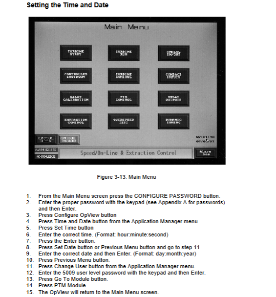
Time and date calibration: Enter the password through the main menu “CONFIGURE PASSWORD” and enter the application manager settings. The formats are “hour: minute: second” and “day: month: year”
Operation steps
(1) General operating rules
Operation method: Touch screen operation, button selection will change brightness or color to confirm response
Unit display: Consistent with the units configured in the programming mode of the 5009 control system (such as displaying KW or MW as load)
Communication loss handling: The screen displays “LOST Communication”, which allows browsing but cannot issue commands. The 5009 control system will generate an alarm, and the alarm needs to be reset to receive the set value after communication is restored
Local/Remote Switching: After configuring 5009, the main menu and dynamic/trend menu display switching buttons, and all screens (except trend screens) display status indicators
(2) Special function operation
Turbine Start: Select the start mode (Idle/Rated, Auto Start Sequence, etc.) through the “Turbine Start” screen, click “START” to issue the start command, and monitor the speed increase status
Turbine operation: Adjust the speed, extraction, and other settings on the “Turbine Run” screen, enable/disable frequency control, synchronizers, and other functions
Controlled Shutdown: Start the shutdown sequence through the “Controlled Shutdown” screen, and click “ABORT” to abort the shutdown
Valve Calibration: Enter the calibration password (1111), meet the permission conditions such as shutdown state and speed<1000RPM, adjust the valve opening through the “Valve Calibration” screen, and click “SAVE CALIBRATION” to save
PID adjustment: Enter the “PID Control” screen to view the output and set values of each PID, and enter the dynamic adjustment password to modify the proportional, integral, and derivative parameters
Overspeed Test: Perform electrical overspeed (TEST 5009 TRIP) or external overspeed (TEST ExternalRNAL TRIP) test on the “Overspeed Test” screen. If the set value is not adjusted within 60 seconds during the test, it will automatically terminate
Alarm Log: View active alarms (red with asterisks) through the “Alarm Log” screen, click “ALM ACK” to confirm, “RESET” to reset, “CLEAR” to clear, and support printer output logs
(3) Permission management
The operation permissions are divided into three levels, and access is required by entering the corresponding password through the pop-up keyboard
Permission level, password, core operation permissions
SUPVAR level 1113 access application manager, configure OpView
Calibration level 1111 dynamically adjusts PID parameters and valve calibration
5009 level 5009 basic monitoring, setting value adjustment, mode switching
It is recommended to restore permissions to level 5009 during normal operation to prevent unauthorized operations
Password information and product support
(1) Password details
SUPVAR Level Password:1113, Used to access the application manager and configure OpView system parameters
Tuner/Valve Calibration Level Password:1111, Used for dynamically adjusting controller parameters and valve calibration operations
5009 Level Password:5009, Used for daily basic operations, such as parameter viewing and issuing regular commands