Woodward DSLC-2 Digital Synchronizer and Load Controller
Basic Information
Core positioning: Integrated controller for synchronization, load, reactive power, power factor, and process control of three-phase AC generators
Applicable scenarios include isolated operation, parallel operation of power grids, and adaptation to industrial computer rooms, ships, and other scenarios
An independent overspeed/overtemperature/overpressure shutdown device is required as a prerequisite for safety, and unauthorized modification of parameters is prohibited
Detailed explanation of core functions
(1) Synchronous control
control mode
Operation mode: Execute synchronization and output circuit breaker closing command
Check mode: Synchronize matching but do not output closing command
Allow mode: Only verify synchronization conditions, manually control speed/voltage
Off mode: Sync function disabled, manual operation
Key functions
Synchronization methods: phase matching (fast synchronization), slip frequency synchronization (ensuring forward power)
Non voltage busbar closing: supports single segment/multi segment closing, avoids conflicts through network arbitration
Voltage matching: Automatically adjust the generator voltage to the bus voltage window (default 0.5%)
Automatic Resynchronization: After the circuit breaker is accidentally disconnected, it can be retried infinitely to close (parameter 7514 needs to be enabled)
Core parameters
Slip frequency offset: 0.02-0.49Hz (default 0.18Hz)
Maximum phase window: ± 60 ° (default ± 7 °)
Circuit breaker delay: 40-300ms (default 80ms), matching the circuit breaker closing time
(2) Load control
control mode
Core purpose of mode triggering conditions
CB Aux in droop mode is disconnected, and there is no RUN/CHECK command for single machine operation or parallel stable operation
Constant frequency load sharing CB Aux closure, load/UNload closure, base load/process control disconnection, multi machine parallel load sharing
Basic load mode CB Aux+Load/UNload+Basic load input closed fixed load operation
Process control mode CB Aux+Load/UNload+Process control input closed tracking process signal (such as inlet and outlet power)
Key functions
Soft loading/unloading: Slope rate 0.01-100%/s (default 3%/s), supports pause (DI09)
Reverse power protection: instantaneous tripping (-50~-1% rated power) or delayed tripping (0.1-20s) can be set
Load limit: High/low load limit (0-150% rated), triggering alarm/relay output when exceeding the limit
Core parameters
Sag coefficient: 0-100% (default 3%)
Unloading trip level: 0.5-99.9% (default 3% rated power)
Load sharing gain: 0.00-100.00 (default 0.50)
(3) Reactive power/PF control
control mode
VAR control: maintain the set reactive power (kvar)
PF control: Maintain the set power factor (-0.5~0.5, default 0.5)
Disable mode: Only retain voltage matching, return to initial voltage bias after matching
Key functions
VAR sharing: When multiple machines are connected in parallel, the reactive load is evenly distributed proportionally
Voltage fine-tuning: Compensate for voltage deviation through PID and stabilize system voltage
Reactive power limit: The reactive power output of the generator is limited to -10%~100% of the rated reactive power (parameter 1758)
Core parameters
Reactive droop coefficient: 0-20% (default 0%)
VAR sharing gain: 0.00-100.00 (default 0.50)
PF reference: -0.999~0.999 (default 0.50)
(4) Process control
Adaptation scenarios: cogeneration, power grid import and export control, pressure/liquid level maintenance, etc
Key functions
Signal input: Supports analog signals such as 0-20mA/4-20mA/0-10V, and can be configured with engineering units (kW/℃/kPa, etc.)
PID control: proportional gain 0.01-100.00 (default 2.00), supports direct/indirect actions
Process filtering: 0-8 levels (default 0 level), suppresses noise signal interference
Core parameters
Process reference: -999999.9~999999.9 (default 0.0)
Reference lifting rate: 0.01-20.00%/s (default 0.10%/s)
Process load sharing coefficient: 1-99% (default 10%)
Hardware and Communication Configuration
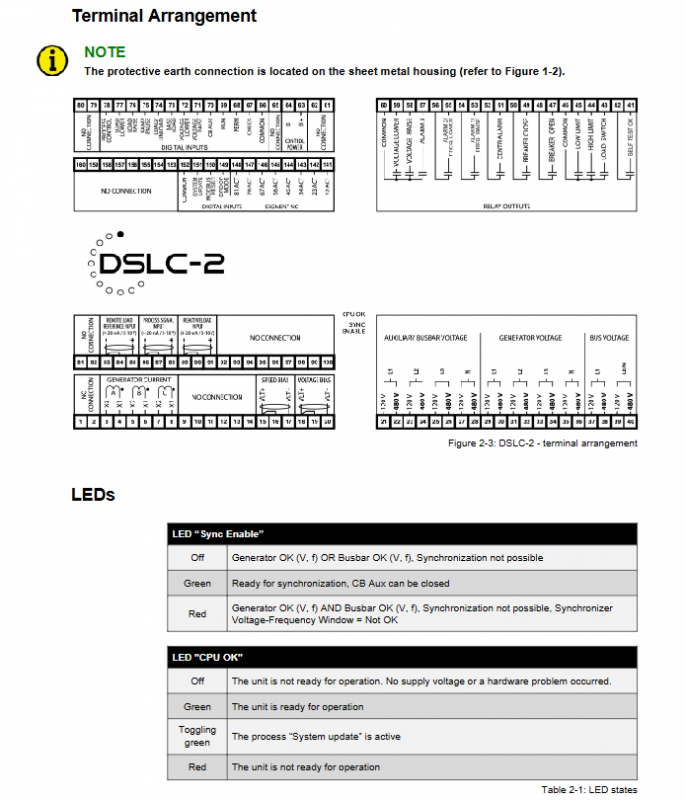
(1) Hardware interface
Measurement input
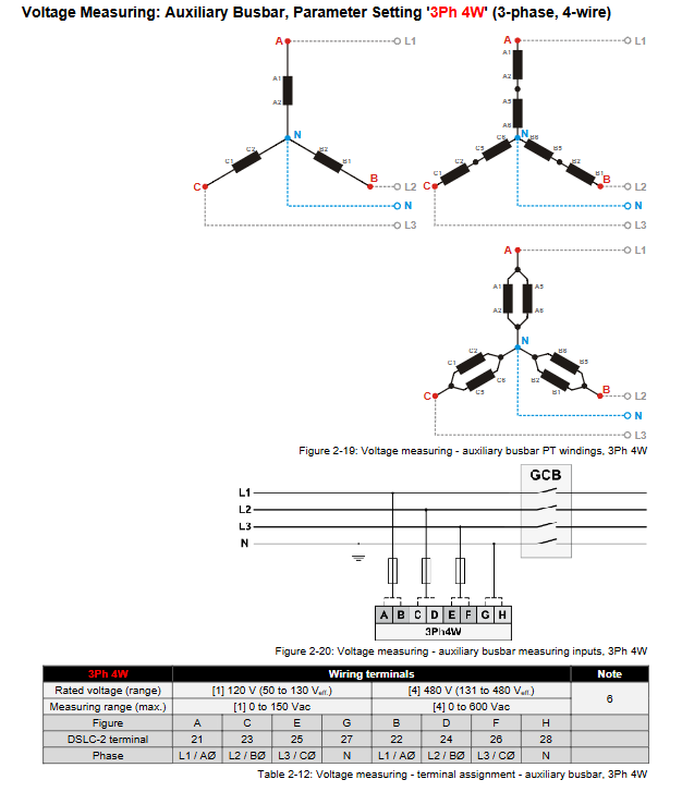
Voltage measurement: Generator (3Ph 3W/4W/4W OD), Bus (1Ph 2W/3Ph), Auxiliary Bus (3Ph 3W/4W)
Current measurement: Generator L1-L2-L3 or single phase to ground, CT ratio 1-32000A/x
Power measurement: supports active power (kW), reactive power (kvar), apparent power (kVA), and PF measurement
I/O interface
Type, quantity, key specifications
Discrete Input (DI) 23 channels support positive/negative signals, with a wire diameter of ≥ 2.5mm ²
Relay output (DO) 12 normally open contacts, used for alarm, circuit breaker control, etc
Analog input (AI) with 3 channels supporting 0-20mA/4-20mA/0-10V/1-5V
Analog output (AO) with 2 speed biases and voltage biases, supporting ± 20mA/± 10V
(2) Communication interface
serial communication
RS-232 (Serial 1): ToolKit configuration (ServLink protocol) Modbus RTU, Baud rate 9.6-115kBd
RS-485 (Serial 2): Modbus RTU slave, supports half duplex/full duplex, slave ID 0-255
Ethernet communication
Dual Ethernet ports (A/B): Supports single mode/redundant mode, configurable IP address (subnet mask 255.255.255.0)
Protocol: Modbus TCP, UDP (device to device communication), up to 10 TCP/IP connections
Redundancy function: In the event of a single network failure, the redundant network will automatically take over and trigger a communication alarm
System networking and segmentation
Network scale
Up to 32 DSLC-2s (generator side) and 16 MSLC-2 (grid/tie circuit breaker side)
Up to 8 segments, supporting two modes of bus segmentation/equipment segmentation
Segmentation rules
The segment numbering needs to be configured in linear order and can be closed into a circular shape
Up to one MSLC-2 can be used as the main controller within the same segment (priority given to the device with the smallest number)
Segmented recognition through DI13-DI20 (segmented activation signal), supporting cross segment non pressure closing
Safety and Diagnosis
Safety Specifications
Electrostatic protection: Discharge before contacting PCB, do not touch components, support 85kV electrostatic spraying
Electrical safety: PE grounding (wire diameter ≥ 2.5mm ²), power circuit connected in series with 6A slow melting fuse
Wiring taboos: CT secondary side must not be open circuited, voltage input must not be short circuited, and different signal types should be wired separately
Diagnostic function
Alarm types: frequency/voltage/load overload, communication failure, missing members, circuit breaker failure, etc
Diagnostic tool: ToolKit real-time monitoring, trend analysis, event recording, supports CSV export
Counter: Operating hours, active/reactive energy counter (can be preset and reset)