What are the core configuration points and networking capabilities
Basic Information
involving models 8440-1922、8440-1923、8440-1924、8440-1925、8440-1930、8440-1931、8440-1932、8440-1933
Core positioning focuses on communication interface configuration (CAN bus Modbus)、 Remote control, data transmission, and diagnosis
Applicable scenarios: ordinary industrial computer rooms, ship generator sets (compatible with LR/ABS classification society certification related ECUs)
The safety prerequisite must comply with the requirements of independent overspeed/overtemperature shutdown devices, and unauthorized modification of equipment parameters is prohibited
Hardware interface configuration
(1) CAN bus interface (2 channels)
CAN interface 1 (freely configurable)
Protocol: CANopen
Transmission components: 5 receive PDOs (RPDO), 5 send PDOs (TPDO), 4 additional Server SDOs
Key parameters: Baud rate 20-1000 kBd (default 250 kBd), Node ID 1-127 (default 1), heartbeat time 0-65500 ms (default 2000 ms)
Function: Load sharing, multi device networking, transmission of set values (frequency/voltage/power, etc.)
CAN interface 2 (engine bus)
Protocol: Supports both CANopen and J1939 simultaneously
Compatible devices: Woodward IKD1, Phoenix expansion module (up to 32 DI/DO, 16 AI, 4 AO)
J1939 support: compatible with 10+ECU models such as S6 Scania and EMR2 Deutz, supporting engine start stop and speed deviation control (0-1400 rpm)
Load sharing parameters: transmission rate 0.10-0.30 s (default 0.10 s), CAN-ID optional 2xx/3xx/4xx/5xx Hex (default 5xx Hex)
(2) Serial interface (2 channels)
Interface type, model, core function, key parameters
RS-232 Serial 1 local debugging Modbus、ServLink、 Modems connect to slave station ID 0-255 (default 1), response delay 0.00-1.00 s (default 0)
RS-485 Serial 2 Modbus RTU Slave, PLC interconnection, remote configuration slave ID 0-255 (default 1), response delay 0.00-2.55 s (default 0)
Core communication function
(1) CAN communication core function
Data transmission mode
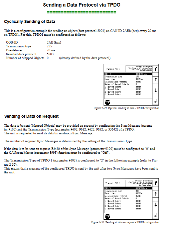
TPDO: Supports cyclic sending (default 20 ms) and on-demand sending (triggered by Sync messages)
SDO: default communication channel+4 additional channels, supports Node ID extension (0-127)
Remote control capability
Basic control: start stop (Bit0/1), alarm confirmation (Bit4), supports RPDO/SDO two modes
Set value transmission: frequency (0-7000 × 0.01 Hz), voltage (50-650000 V), power factor (-710-1000-710), active power (0-999999 × 0.1 kW)
Multiple setting value transmission: A single PDO can map 3 objects (such as frequency+power+power factor)
Diagnostic function
Load diagnosis: More than 21 messages within 20 ms trigger ‘CAN bus overload’, automatically disabling the bus until the load drops below 22 messages/20 ms
Status diagnosis: Monitor PDO mapping errors, Node ID conflicts, RPDO receive timeouts, etc
(2) Modbus communication core function
Address planning
Configuration/control area: 40001-450000, supports single register/multi register writing
Visualization area: Starting from 450001, supports reading 1-128 register blocks (including electrical parameters, alarm status, etc.)
core operation
Remote control: Implement start stop and alarm confirmation through parameter 503 (address 40504)
Set value modification: Switch the second set of set values (voltage/frequency/power, etc.) through parameter 504
Maintenance functions: Clear event history (parameter 1706), reset default values (parameter 1701), single alarm confirmation (parameter 522)

Data type adaptation
Basic types: UNSIGNED8/16/32, INTEGER16/32 (occupying 1-2 registers)
Special types: LOGMAN (7 registers), TEXT (length/2 registers)
Data protocol and ECU adaptation
(1) Core Data Protocol
Protocol Number Usage Key Content
4103 diagnostic fault code includes DM1 (10 active DTCs), DM2 (10 historical DTCs), SPN/FMI/OC information
5003 Control and Measurement Data Generator Voltage (0.1 V accuracy), Frequency (0.01 Hz accuracy), Battery Voltage, etc
5010 visualization data covers generator/grid/bus electrical parameters, alarm status, engine operation data (445+items in total)
6000 load sharing messages support networking of 32 devices, including power allocation and synchronization signals
(2) J1939 ECU adaptation
Supports 10 ECU models including Woodward EGS, MTU ADEC, Volvo EMS2, etc
Remote control functions: engine start stop, idle mode, 50/60Hz switching, speed deviation adjustment, etc
Data collection: supports 20+parameters such as engine speed (0.1 rpm accuracy), coolant temperature (1 ℃ accuracy), etc
Safety and fault handling
Safety Specifications
Electrostatic protection: discharge before contacting the circuit board to avoid plastic/foam materials close to PCB
Power operation: Turn off the charging device before disconnecting the battery, and connect the power line in series with a 6A slow melting fuse
Parameter modification: A password of level 2 or above is required, and the modified values must be within the set range (such as baud rate, Node ID)
Common troubleshooting
CAN communication: No data transmission required. Check if the device is in operation mode and PDO parameter configuration
Modbus communication: Address error requires confirmation of protocol agreement (some PLCs require address+1), function code support (only 03/06/10)
Bus conflict: Node ID duplication will trigger CAN2 status Bit13 alarm, ID needs to be reassigned
Key issues
Question 1: What are the core configuration points and networking capabilities of the CAN bus interface of the easyYgen-3000 series in load sharing scenarios?
Answer: The core configuration and networking capabilities focus on three points: ① Hardware limitations: up to 32 devices can be networked, and the CAN2 interface is dedicated for load sharing, requiring configuration of transmission rate (0.10-0.30 s) and CAN-ID (2xx/3xx/4xx/5xx Hex); ② Parameter consistency: All participating devices need to have a unified baud rate (default 250 kBd), Node ID (recommended low value), and load sharing interface (default CAN1); ③ Bus load control: It is recommended that the total load not exceed 100%, which can be optimized by increasing the baud rate, reducing the frequency of visual data transmission, and disabling redundant Sync/TIME messages. Suitable for power balance allocation scenarios of small and medium-sized generator clusters.
Question 2: How to achieve remote control of generator set start stop and parameter modification in Modbus communication, and what are the key addresses and operating logic?
Answer: ① Remote start stop: Operated through Modbus address 40504 (parameter 503), Bit0 is set to 1 to start, Bit1 is set to 1 to stop, and Bit4 needs to be set to 1/reset twice to complete alarm confirmation; ② Parameter modification: Basic parameter (such as generator rated voltage) address=40000+parameter ID+1 (parameter ID<10000) or 400000+parameter ID+1 (parameter ID ≥ 10000), the corresponding interface password needs to be entered first (such as serial port 1 password parameter 10401); ③ Setpoint switching: To enable the second set of voltage/frequency/power factor/power setpoints through Bit4-7 at address 40505 (parameter 504), the setpoint source needs to be configured as “Interface” first. The operation must follow the Modbus RTU protocol and support single register (function code 06) or multi register (function code 10) writing.
Question 3: What are the adaptation capabilities and core interaction functions of the easyYgen-3000 series for J1939 ECU, and what should be noted during the adaptation process?
Answer: Adaptability and interactive functions: ① Compatibility range: Supports 10+mainstream ECUs (such as Scania S6, Deutz EMR2), which can achieve 8 core functions including engine start stop, idle control, and speed deviation adjustment (0-1400 rpm) through CAN2 interface; ② Data exchange: Collect 20+parameters such as engine speed and coolant temperature, and support DM1/DM2 fault code transmission; ③ Attention: Select the corresponding ECU model in parameter 15102 (device type). The J1939 self address (parameter 15106) defaults to 234, and the engine control address (parameter 15107) defaults to 0; Even if the ECU is not connected, if the J1939 analog input device is connected, the device type cannot be set to “Off”, and some ECUs require the manufacturer to enable remote control function.