Woodward ProTech-SX Simplex System
Woodward ProTech SX Simplex System (Product Manual 26546V2, Version A) is a safety protection system for engines, turbines, and other prime movers. Its core functions include overspeed/over acceleration protection, fault monitoring, and alarm, supporting 7 configurable inputs and 3 programmable relay outputs+1 4-20mA analog output. It has two levels of password permissions (test level/configuration level) and can be configured and tested online/offline through the front panel interface or programming configuration tool (PCT). It is compatible with Modbus communication, can record multiple logs, and provide fault diagnosis. Throughout the process, it must comply with safety operating standards to avoid personal injury or equipment damage.
Core functions and system features
Protection and monitoring core
Core protection: overspeed protection (set range 0-32000 RPM), over acceleration protection (0-25000 RPM/s)
Fault monitoring: speed loss, open circuit of speed sensor, power failure, internal module failure, etc
Status indication: Front panel LED (trip red light, health green light, alarm yellow light)+remote limit switch feedback
Input/output configuration
Input: 7 configurable inputs, supporting analog (4-20mA) or discrete signal types
Output: 3 programmable relay outputs( 1A@30Vdc )1 channel 4-20mA analog output (proportional to speed)
Permissions and Security Mechanisms
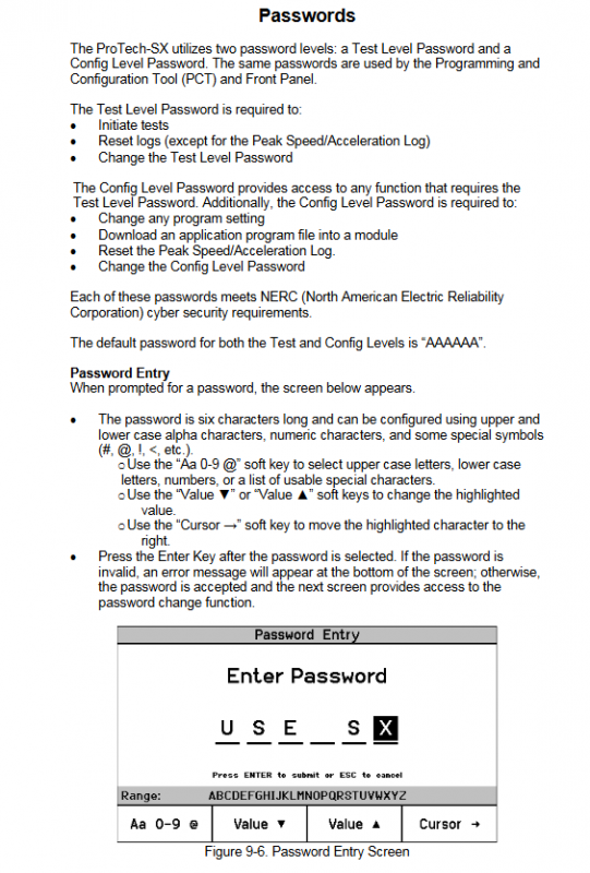
Password permission: Two level password (test level, configuration level), default is AAAAAA
Test level: Start testing, reset logs (excluding peak speed/acceleration logs), modify test level password
Configuration level: All test level functions+modify program settings, download configuration files, reset all logs
Security requirements: Compliant with NERC network security requirements, password supports letters, numbers, and special symbols (6-digit length)
Communication and Compatibility
Communication protocol: Modbus (slave mode), supports RS-232/RS-485 mode
Baud rate options: 19200/38400/57600/115200 bits/s, slave addresses 1-247
Detailed explanation of key operation modules
(1) Front panel interface operation
Key operations of module core functions
Monitor menu to view real-time data, configuration parameters, status indicators, browse RPM, acceleration, analog output, etc; View module information, date and time
Log viewing and retrieval of various event records support 8 types of logs, including overspeed/acceleration logs, trip logs, alarm logs, etc; Resettable log (password required)
Configuration menu basic parameter configuration setting speed input, startup logic, trip latch mode, analog output scaling, Modbus parameters
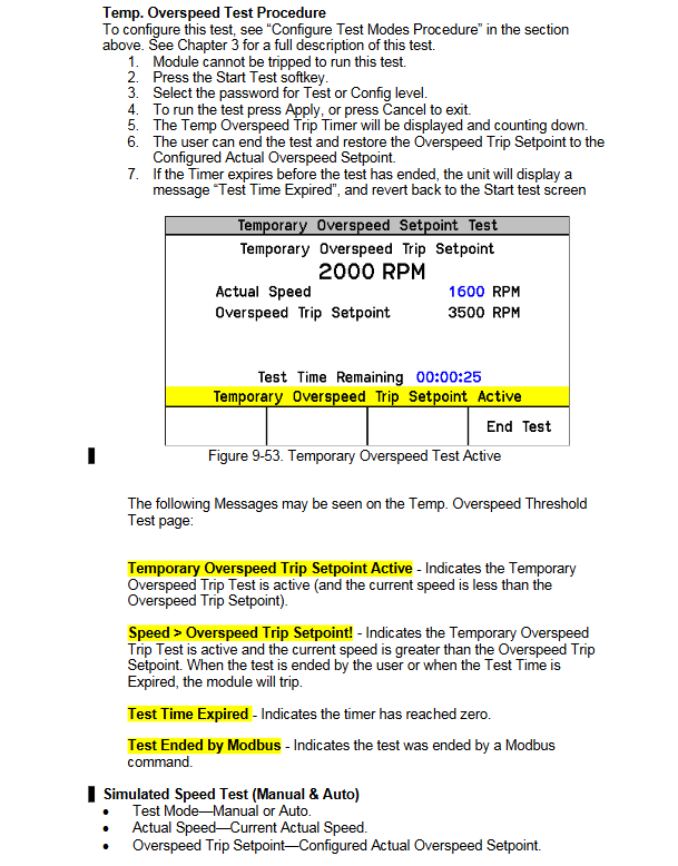
Test mode system function verification includes temporary overspeed test (<32000 RPM), simulated speed test (manual/automatic), 3 sets of user-defined tests, and indicator light test
(2) Programming Configuration Tool (PCT) Operation
PCT Basic Information
Installation method: Download from Woodward installation CD or official website (www.Woodward. com/software)
Operating environment: Based on Woodward ToolKit software, supporting Windows system
Operation level: offline mode (no device connection), testing level (online viewing/exporting logs), configuration level (online configuration modification)
core functionality
Configuration function: Modify parameters online (in device trip state)/offline, support custom logic programming such as logic gates, latches, timers, etc
Log management: View and export logs of trips, alarms, module failures, etc. (supports HTML format)
Configuration verification: Verify configuration consistency through CRC code and detect configuration errors (such as logical loops and input-output mismatches)
(3) Key configuration parameter description
Default value range for core parameters of configuration category
Speed Management Speed Redundancy Mode Single Speed/Double Redundancy Speed Single Speed
Maximum speed difference 0-32000 RPM 100 RPM
Overspeed trip setting 0-32000 RPM 1000 RPM
Start logic speed failure set point 0-25000 RPM 1000 RPM
Speed failure timeout time 1-28800 seconds 10 seconds
Simulate output 4mA corresponding to speed 0-32000 RPM 0 RPM
20mA corresponds to a speed range of 0-32000 RPM and 32000 RPM
Modbus configuration communication mode RS-232/RS-485 RS-232
Allow command writing Yes/No No
Test mode details
Test Type Test Purpose Key Parameter Operation Requirements
Temporary overspeed test verification overspeed trip function test set point 0-32000 RPM, timeout 0-1800 seconds device does not trip, test level/configuration level password required
Manual simulation speed test simulates overspeed scenario starting speed=trip set point -100 RPM, timeout 0-1800 seconds manually adjust simulation speed to trip point
Automatic simulation speed test, automatic verification of trip response, automatic ramp to trip set point without manual intervention, no timeout limit
User defined test validation supports 3 sets of tests for custom logic, configurable start/reset input, timeout time needs to be configured through PCT logic
The indicator light test verifies that the front panel LED cycle lights up the red light (trip), green light (health), and yellow light (alarm) without the need for a password, and can be executed at any time
Safety operation standards
Pre security requirements
Equipment protection: The prime mover needs to be equipped with an independent overspeed shutdown device to avoid the risk of loss of control
Personal protection: Wear goggles, safety helmets, gloves and other PPE during operation
Electrostatic protection: Discharge before coming into contact with electronic components to avoid plastic/vinyl materials coming into contact with circuit boards
Operation restrictions
Configuration modification: The configuration can only be modified when the device is in a tripped state, otherwise operation is prohibited
Password management: Password forgotten cannot be reset, need to return to Woodward for processing
Unauthorized modification: Modifications beyond the rated parameter range are prohibited, otherwise the warranty and certification effectiveness will be lost
Key issue
Question 1: What are the configuration methods for ProTech SX system and what are the core configuration limitations?
Answer: The system supports two configuration methods: ① Front panel interface configuration, which can modify basic parameters such as speed input, startup logic, and analog output; ② Programming Configuration Tool (PCT) configuration, supports online (device needs to trip+configuration level password) and offline configuration, customizable logic (logic gates, timers, etc.) and exported logs. The core configuration restrictions include: configuration modifications must be made while the device is in a tripped state; PCT online configuration requires establishing a serial communication link and entering a configuration level password; Configure to avoid logical loops (by inserting unit delay blocks for cracking); The input and output types need to match (analog inputs cannot be connected to logic gates, discrete inputs cannot be connected to comparators), otherwise configuration errors will be triggered.
Question 2: What types of log management functions does ProTech SX include, and how do I reset or export logs?
Answer: The log types include 8 types of core logs: overspeed/acceleration log, trip log, alarm log, trip cycle time log, event log (3 groups), and peak speed/acceleration log. Log operation method: ① Reset log: It can be operated on the front panel or PCT. Resetting “all logs” requires a test level/configuration level password, while resetting “peak speed/acceleration logs” only requires a configuration level password; ② Export logs: Only through the PCT tool, it supports saving logs as HTML format files, which can view detailed information such as event ID, timestamp, and first out fault; ③ Log features: The timestamp is based on the internal clock at the time of the event occurrence, and modifying the system time does not affect the historical log. A single type of log can store up to 50 events.
Question 3: What are the testing modes of ProTech SX, and what are the applicable scenarios and operational requirements for different tests?
Answer: The system includes four types of testing modes, and the applicable scenarios and operational requirements are as follows: ① Temporary overspeed test: suitable for verifying the tripping response of the actual hardware speed signal, the device speed needs to be increased to the testing set point within the test timeout (0-1800 seconds), and a test level/configuration level password is required; ② Simulated speed test (manual/automatic): suitable for verifying trip logic when there is no actual speed. Manual mode requires manual adjustment of simulated speed, while automatic mode automatically accelerates to the trip point. Both require a password and the device has not tripped; ③ User defined testing: suitable for verifying custom logic (such as tripping/alarm triggered by specific faults), requires PCT configuration to start/reset conditions, supports 3 independent tests; ④ Indicator light test: suitable for quickly verifying the function of the front panel LED, no password required, can be executed at any time, and the red/green/yellow LED lights up cyclically.