ABB MicroFlex servo drive
Core parameters of the product
Category key specifications specific parameters
Current specification: Continuous output current of 3A/6A/9A (RMS)
Peak output current 6A/12A/18A (continuous for 3 seconds)
Voltage parameter main circuit input 115-230VAC (single/three-phase), 105-250VAC wide range
Control circuit input 24VDC (compatible with 20-30V), 4A startup impulse current
DC bus voltage 305V (115VAC input)/321V (230VAC input)
Control performance control mode: torque control, speed control, position control (pulse+direction)
Maximum pulse frequency 1MHz (position control)
Feedback resolution rotary transformer 4096PPR (configurable 1024PPR), encoder up to 8MHz
Environmental adaptation working temperature 0-45 ℃ (normal), 45-55 ℃ (linear derating)
Storage temperature -40-85 ℃
Humidity limit 93% RH (no condensation)
Installation at an altitude of 1000m (with a capacity reduction of 1.1% for every 100m beyond 1000m)
Installation and wiring specifications
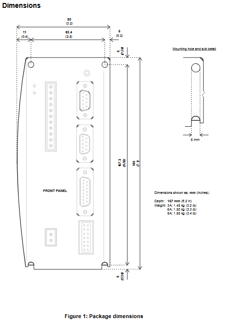
(1) Mechanical installation requirements
Installation method: Vertically installed on the metal backplate to ensure that the heat dissipation surface is in close contact
Spacing requirements: Side ≥ 15mm, up and down ≥ 90mm, front ≥ 60mm (wiring space)
Cooling requirement: 3A model naturally cooled; The 6A model requires forced air cooling at 1-1.5m/s; 9A model requires forced air cooling at 1-3.5m/s
Capacity reduction feature: For every 1 ℃ increase above 45 ℃, the output current is reduced by 2%
(2) Electrical wiring details
Power wiring:
Main circuit: L1/L2/L3 connected to input power supply, U/V/W connected to motor winding, R1/R2 connected to braking resistor
Protection configuration: Recommend using Ferraz Shawmut series fuses (3A model 10A/8A, 6A model 20A/12.5A, 9A model 25A/20A)
Grounding requirements: protective grounding conductor ≥ 2.0mm ² (copper), maximum grounding leakage current 3.4mA/phase
Feedback wiring:
Incremental encoder: X8 interface (15 pins), CHA ±/CHB ±/CHZ ± differential signal, supports Hall signal input
SSI encoder: X8 interface (15 pins), Data ±/Clock ± differential signal, longest cable 30.5m
Rotary transformer: X8 interface (9 pins), REF ±/COS ±/SIN ± signal, equivalent resolution 4096ppr
Signal wiring:
Analog input: X3 interface AIN0 ±, ± 10V range, 12 bit resolution
Digital I/O: X3 interface (driver enable, universal input, pulse+direction, status output)
Serial communication: X6 interface (RS232/RS485), default 57.6Kbaud, supports multi machine networking
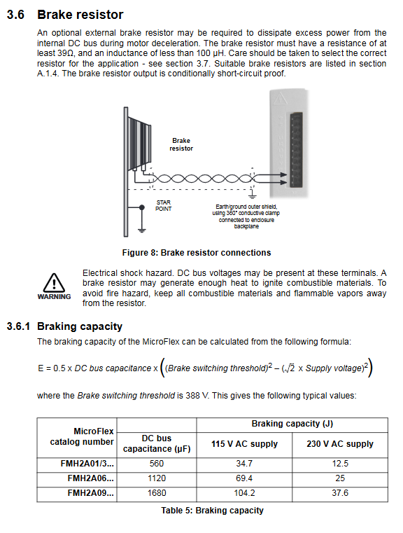
(3) Selection of braking resistor
Minimum resistance: 39 Ω (to avoid overcurrent damage to the driver)
Recommended models: RGJ139 (39 Ω/100W), RGJ160 (60 Ω/100W), RGJ260 (60 Ω/200W), RGJ360 (60 Ω/300W)
Requirements for Capacity Reduction: Capacity reduction is required in free air environments (for 100W models, capacity reduction is required at 25 ℃ to 80% and 55 ℃ to 70%)
Configuration and Debugging Process
(1) Software Tools
Essential software: Mint WorkBench (supporting Windows XP and above systems)
Hardware requirements: The PC requires a 1GHz processor, 512MB of memory, 2GB of hard drive, and a serial port (RS232/RS485)
Core functions: Commissioning Wizard, Fine tuning, Parameters, Scope
(2) Debugging steps
Hardware connection: The PC is connected to the driver through a serial port cable (X6 interface), and the 24VDC control power supply and main circuit power supply are connected
Software startup: Install Mint WorkBench, create a new project, scan and connect drives
Wizard configuration: Use the Commissioning Wizard to select the control mode, motor model, and feedback type, and automatically complete parameter tuning
Fine tuning optimization: Adjust the gain of the current/speed/position loop using Fine tuning tools and perform testing motion to verify performance
Parameter saving: Save configuration parameters to the non-volatile memory of the drive to avoid power loss
(3) Control mode description
Control mode signal source, core purpose, key parameters
Torque control analog input/software command constant torque output scene torque constant, current loop gain
Speed control analog input/software instruction constant speed operation scenario speed loop gain, acceleration/deceleration time
Position control pulse+direction input precision positioning scene electronic gear ratio, position loop gain
Troubleshooting and Maintenance
(1) Fault indication and handling
Key points for troubleshooting status LED fault types
Red flashing (1-12 times) corresponds to error codes (1=phase search error, 3=overcurrent, etc.). Check AXISOROR/DRIVEERROR parameters and wiring/load
Red green alternating flashing undervoltage warning. Check if the main circuit power supply is connected and if the DC bus voltage is ≥ 50V
Check the wiring of the 24VDC power supply to ensure that the voltage is within the range of 20-30V when the control power supply fails to light up
(2) Common problem solving
Communication failure: Confirm that the PC serial port selection is correct, use the “scan all serial ports” function, and check the serial port cable wiring
Driver unable to enable: Check if the X3 interface driver enable signal (6/7 pins) is valid and clear the fault status
Motor instability: Reduce the speed loop proportional gain (KVPROP) and confirm that the current loop parameters match the motor
(3) Maintenance points
Regular inspection: Check if the heat dissipation duct is unobstructed, if the temperature of the braking resistor is normal, and if the cable shielding layer is intact
Cable maintenance: The distance between feedback cables and power cables should be ≥ 76mm, avoiding parallel wiring and maintaining a 90 ° angle when crossing
Software maintenance: Regularly update Mint WorkBench version, backup drive configuration parameters
Accessories and Compliance Information
(1) Key accessories
Accessory type, model, example, function, and purpose
Cooling fan FAN001-024 provides forced air cooling for 6A/9A models, meeting UL certification requirements
EMC filter FI0029A00 suppresses electromagnetic interference and complies with CE directive requirements
The RGJ series braking resistor consumes braking energy to avoid bus overvoltage
Special cable CBL025SP-12 motor power cable/feedback cable with shielding layer
(2) Compliance requirements
CE compliance: EMC filter needs to be installed, motor cable length ≤ 30m, shielding layer grounded 360 °
UL compliance: Use recommended fuses to protect grounding conductors with a minimum of 2.0mm ²
RoHS compliance: Restrictions on harmful substances such as lead and mercury, product labeling complies with SJ/T 11364-2014 standard