Baldor MotiFlex e100 servo drive
1. Product Overview
Model and basic information: Baldor MotiFlex e100 servo drive, suitable for closed-loop vector control of rotary/linear motors and induction motors, offering a variety of continuous current models from 1.5A to 65A.
Core Features:
Power supply support: 230-480VAC three-phase input, supports DC bus sharing to reduce wiring and device requirements.
Feedback method: Compatible with various feedback interfaces such as incremental encoder, BiSS, EnDat, SSI, SinCos, etc.
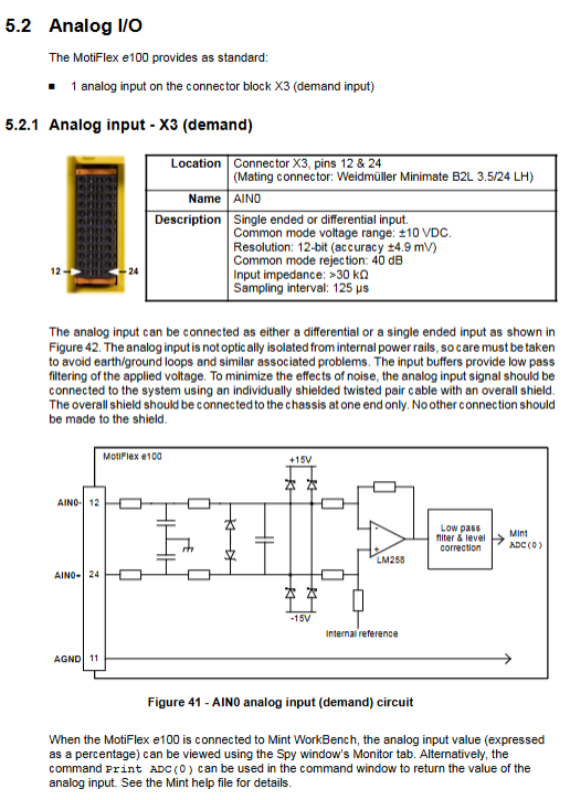
I/O configuration: 3 universal digital inputs (including 2 high-speed inputs), 1 dedicated driver enable input, 2 digital outputs, 1 analog input (± 10V), and 1 motor overheat input.
Communication interfaces: USB 1.1, RS485, Ethernet (TCP/IP+POWERLINK), CANopen.
Control modes: position control, speed control, torque control, supporting pulse/direction input and fast position capture.
Applicable scenarios: Variable speed control of industrial fixed equipment, prohibited for household appliances, medical equipment, mobile carriers, and other scenarios.
2. Installation process
2.1 Installation Preparation
Environmental requirements:
Environmental parameter specification requirements
Operating temperature 0-45 ℃ (with a 1 ℃ decrease in capacity for every 1 ℃ increase in temperature between 45-55 ℃)
Relative humidity<93% (non condensing, below 45 ℃)
Altitude ≤ 1000m (over 1000m, capacity reduction of 1.1% per 100m)
Protection level IP20 (to be installed in electrical cabinets or with protective barriers)
Hardware requirements:
Equipment/tool specification requirements
Minimum PC: Pentium III 500MHz, 256MB RAM, 100MB hard drive; Recommendation: Dual core 2GHz, 1GB RAM
Cable motor power line (shielded twisted pair, up to 30.5m), feedback cable (22AWG shielded twisted pair)
Tools: Screwdrivers below 2.5mm, M5 bolts, crimping tools
Optional accessories include EMC filter, DC busbar, regenerative resistor, cable management bracket
2.2 Key Connection Steps
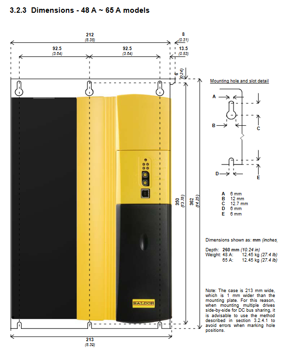
Mechanical installation: Vertically fixed on the metal surface, a 90mm heat dissipation space should be reserved at the top/bottom for single installation, and the spacing between multiple units should be ≥ 13mm. When sharing DC busbars, precise alignment is required to install the busbars.
Electrical connection:
Power connection: The three-phase input is connected to L1/L2/L3, and the PE grounding requires a wire of ≥ 10mm ²; When sharing the DC bus, only the source driver is connected to the AC power supply, and the receiving driver is powered through the bus bar.
Motor connection: U/V/W corresponds to the motor winding, and the shielding layer is grounded 360 °; The motor circuit can be disconnected through a contactor (the driver needs to be disabled 20ms in advance).
Feedback connection: Connect according to the feedback type (encoder/BiSS, etc.), use twisted pair for signal pairing, single ended grounding for shielding layer, and the longest cable is 30.5m.
Regenerative resistor: minimum 60 Ω for 1.5A/3A model, minimum 15 Ω for 21A/26A model, keep away from flammable materials and reserve heat dissipation space.
Backup power supply for control circuit: optional 24VDC input (20-30VDC, 1.2A maximum current), used to retain position/I/O information when AC power is cut off.
3. Operation and Configuration
3.1 Software Operation
Software installation: Install Mint Machine Center (MMC) and Mint WorkBench v5.5, supporting Windows XP/Vista/7 systems.
Debugging process:
Connect the PC to the driver (USB/Ethernet) and install the USB driver (Windows auto recognize).
Start the Commissioning Wizard, select the motor model, configure the control mode (position/speed/torque), and set the scaling factor (such as revolutions per degree).
Run Autotune Wizard to automatically tune (with or without load) and optimize current/speed/position loop parameters.
Perform test movement: jog (JOG (0)=10), relative positioning (MOVER (0)=10+GO (0)), monitor status through Spy window.
3.2 Core Function Configuration
DC bus sharing: The source driver needs to be configured with a “Power Ready” output, and the receiving driver needs to be configured with the corresponding input. A specified inductor (such as a 1.5A model with 1.2mH) needs to be installed.
Control mode:
Position control: Supports preset movement, electronic gear, origin regression, and configurable tracking error threshold.
Speed control: Set the speed through analog input or communication, and support PID regulation.
Torque control: It should be noted that the motor may overspeed when there is no load, and the maximum speed should be limited.
Digital I/O configuration: High speed input can be set as pulse/direction or fast position capture, and output can be set as motor brake control, fault indication, etc.
4. Troubleshooting and Safety Standards
4.1 Common fault handling
Troubleshooting direction
Status LED flashes red to check for error codes (e.g. 3 flashes=overcurrent), locate using the Error Log tool
Communication failure check USB/Ethernet cable, confirm IP configuration (Ethernet default 192.168.100.xxx)
Motor instability, execute Autotune again, reduce bandwidth parameters, check load coupling condition
CANopen bus fault confirmation: Terminal resistance (120 Ω), consistent baud rate for all nodes, unique node ID
4.2 Safety Regulations
It must be operated by professional personnel. After power failure, wait for 5 minutes for discharge before touching the power terminal.
The wiring complies with NEC/CE standards, with separate wiring for power and control lines, intersecting at a 90 ° angle, and the shielding layer reliably grounded.
The working temperature of the regenerative resistor may exceed 80 ℃, and it should be kept away from flammable materials; The motor brake requires an independent 24VDC power supply to avoid noise interference.
5. Summary of Technical Specifications
Category key parameters
Power supply input three-phase 230-480VAC (180-528VAC range), DC bus voltage 325V (230V input)/678V (480V input)
Output characteristics: Continuous current of 1.5A-65A, output frequency of 0-2000Hz, switching frequency of 4/8/16kHz (some models)
Feedback accuracy incremental encoder supports up to 8MHz, absolute encoder supports multi turn positioning
Environmental protection: shock resistance of 10G, vibration resistance of 1G (10-150Hz), storage temperature -40-85 ℃