Watlow Anafaze SYSTEM 32 Modular Industrial Process Controller
1. Product Overview
Core positioning: SYSTEM 32 is a modular industrial process controller designed with plug-in modules, focusing on multi loop PID control and data acquisition. It is suitable for industrial processes such as temperature, pressure, and flow, and supports single or multi machine networking operation.
Core Features:
Control capability: 32 independent PID control loops, supporting four control modes: ON/OFF, P, PI, and PID. Each loop can independently set control actions (forward/reverse).
Modular design: The core modules include processor I/O module (A32-PPIOM), analog input module (A32-RHAIM/SSAIM), analog output module (A32-AOM), pulse input module (A32-PIM), supporting 16-96 analog input expansion.
Communication interface: Supports RS-232 (up to 50 feet), RS-485 (up to 6000 feet), 20mA current loop (up to 5000 feet), and up to 16 devices can be networked.
Software support: ANASOFT-32 menu driver software, supporting parameter configuration, data recording, Ramp/Soap batch control, compatible with IBM PC and compatible machines.
2. Installation process
2.1 Installation Preparation
Environmental requirements:
Environmental parameter specification requirements
Working temperature 0-50 ℃ (32-122 ° F)
Relative humidity 10% -90% (non condensing)
Installation method: 3 slots (10.7 inches wide)/6 slots (19 inches rack mounted) housing
Power input 120VAC 60Hz (power module output 5VDC 5A)
Core modules and hardware:
Module Model Function Description Key Parameters
A32-PiOM processor I/O module (core) with 32 digital outputs and 16 digital inputs
A32-RARIM reed relay analog input module with 16 inputs and 250Vdc channel isolation
A32-SSAIM solid-state analog input module with 32 inputs and 15Vdc channel isolation
A32-AOM analog output module with 16 outputs (4-20mA/0-5V optional)
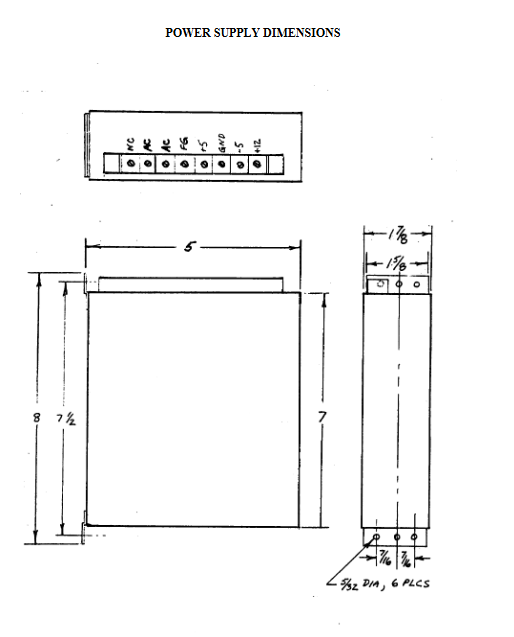
A32-PS power module input 120VAC, output 5VDC 7A
2.2 Key installation steps
Mechanical installation: Choose a 3-slot or 6-slot housing, insert the module into the card slot and secure it, ensuring that there is no obstruction between the modules and ensuring heat dissipation.
Electrical connection:
Power supply: Connect 120VAC to the power module (A32-PS), output 5VDC to power other modules through the backplane, and connect an external 1/2A fuse.
Sensor: Thermocouple (J/K/T/R/S/B type) directly connected, 4-20mA signal needs to be connected in series with a 3k Ω resistor, RTD recommends 3/4 wire system.
Communication: RS-485 requires shielded twisted pair cables with a 200 Ω terminal resistor at the end; When multiple machines are connected to the internet, the address is set to 0-15 (DIP switch 1-4 bits).
Address and parameter settings: Set the address (1-4 bits), communication baud rate (6 bits), and error check (7 bits) through the 8-bit DIP switch on A32-PiOM.
3. Operation and Configuration
3.1 Core Configuration
PID parameter tuning:
Mode selection: Supports ON/OFF, P, PI, PID modes, default recommended parameters: P mode PB=5% SP, PI mode PB=10% SP+TI=120 seconds, PID mode PB=15% SP+TI=60 seconds+TD=12 seconds.
Output types: digital output (ON/OFF, cycle ratio, distributed zero crossing), analog output (4-20mA/0-5V).
Module address setting: Set the address (0-15) through DIP switch 1-4 bits, support networking of 16 devices, default address 0 (fully closed).
Communication parameter configuration: baud rate 2400/9600 (DIP switch 6 bits), error check BCC/CRC (DIP switch 7 bits), consistent with ANASOFT-32 software.
3.2 Software Operation (ANASOFT-32)
Core functions: parameter configuration (PID/input type/alarm), real-time data display, data recording (LOTUS compatible files), Ramp/Soak batch control (16 segments/configuration files).
Advanced features: Open heater detection, communication watchdog timer (default timeout of 120 seconds, can be set to 1-1092 seconds), global alarm output.
4. Troubleshooting and Safety Standards
4.1 Common fault handling
Troubleshooting direction
The processor ready light (green) is not on. Check if the 5VDC power supply (4.9-5.3V) and power module are working properly
The communication light (orange) is not on. Check the address, baud rate, and error verification parameters, and inspect the communication cable wiring
Control output no response confirmation TB2 pin 35 (Output ON) grounded to enable output, check watchdog timer status
Abnormal measurement value check sensor wiring, input module indicator light (green=normal power supply, orange flashing=scanning), calibration parameters
4.2 Safety Regulations
Mandatory requirement: It must be equipped with an external independent safety device to prevent controller failure from causing full on/off output.
Operation taboos: Power off before module insertion and removal, keep sensor cables away from power lines, and ground the shielding layer of communication cables at one end.
Anti static: Wear an anti-static wristband when installing modules to avoid touching circuit board components.
5. Summary of Technical Specifications
Category key parameters
Input characteristics 16-96 analog inputs, resolution 0.02%, support thermocouple/RTD/4-20mA/0-10V
Control output: 32 digital outputs (5VDC 6mA), 16 analog outputs (4-20mA/0-5V)
Communication interface RS-232 (50ft), RS-485 (6000ft), 20mA current loop (5000ft), baud rate 2400/9600
Physical parameters: 6-slot housing: 19 x 12.5 x 7.5 inches, maximum weight of 20 pounds; 3 slots housing: 10.7 x 12.5 x 7.5 inches
Warranty period of 90 days (excluding human damage and modification)