Watlow PPC-2000 Controller
PPC-2000 User’s Guide “is a user manual for modular programmable process control systems launched by Watlow. It supports 48 PID control loops or 8 adaptive control+24 PID control (a total of 32 loops), with rich I/O interfaces (up to 128 analog inputs, 288 digital I/O, 48 analog outputs), supports multiple sensors such as thermocouples and RTDs, and is configured and monitored with ANAWIN3 HMI software. LogicPro software supports logic programming and provides advanced functions such as RS-232/RS-485 communication, adaptive control, and cascade control. The warranty period is 3 years, and it needs to be used in conjunction with external safety devices. The manual covers the entire process of installation, operation, settings, and troubleshooting.
Core specification parameters
1. Control ability
Basic control: Supports On/Off, P, PI, PID control, with built-in Autotune function
Optional configuration: ① 48 channel conventional PID control; ② 8-channel adaptive control+24 channel PID control (a total of 32 channels)
Adaptive Control: Only 1-8 channels are supported, and adaptive mode, system delay (1-600 seconds), and set gain (5 selectable levels) can be set
2. I/O interface parameters
Key parameters of interface type
Up to 128 analog inputs are supported, including thermocouples (J/K/T/B/S/R, etc.), RTDs (100 Ω platinum resistors), 0-20mA/4-20mA currents, and -10V~10V voltages
The maximum number of digital I/O channels is 288, and the processor module comes with 48 channels (24 channels can be configured). The expansion module supports 16/32 input/output channels
Up to 48 analog outputs, supporting 0-5V/0-10V/1-5V voltage and 0-20mA/4-20mA current, expandable through SDAC module
Counter input up to 17 channels, supports 0-10kHz frequency, 16 bit counting range
3. Communication and Power Supply
Communication parameters: RS-232 (maximum 50 feet), RS-485 (maximum 6000 feet), baud rate 9600/19200, Modbus RTU protocol
Power specification: PPC-IPS-2 input frequency 47-440Hz, peak output 9A@5Vdc The 6A@24Vdc Module operating voltage 12-28Vdc
Installation Guide
1. Module installation requirements
Core modules: PPC-2010 processor (48 digital I/O channels, 2 serial ports), PPC-202x analog input module (16/32 channels), PPC-2030 encoder input+analog output module, etc
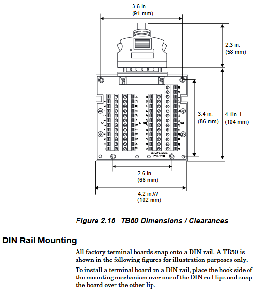
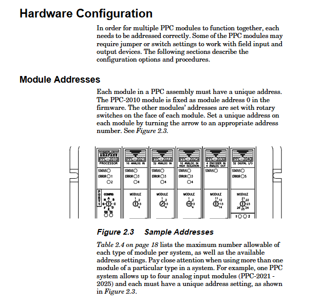
Installation method: DIN rail or panel installation, unique module address (rotary switch setting, 1-64)
Space requirements: Each module should reserve heat dissipation space, PPC-IPS-2 should be installed vertically, and the minimum ventilation space should be 2.5 inches
2. Wiring specifications
Wire gauge requirements: 20-22 AWG shielded wire for analog signals, 24 AWG wire for digital signals, and 12-24 AWG wire for power supply
Shielding treatment: The shielding layer is grounded at one end (controller side) to avoid grounding loops
Sensor wiring: The positive and negative poles of the thermocouple correspond correctly. For 3-wire RTDs, attention should be paid to compensating for lead resistance. Current sensors should be connected in series with matching resistors
3. Environment and Safety
Working environment: temperature 0-60 ℃, storage temperature -20-70 ℃, humidity 10-95%, non condensing, altitude up to 2000 meters
Safety protection: Pollution level 2 (IEC 664), independent power-off switch needs to be installed to avoid live operation
Software operation and function settings
1. ANAWIN3 software operation
Core functions: Configure input types, linear scaling, channel parameters (PV source, output target, PID parameters), alarm settings
Display modes: bar chart, single loop, scanning, alarm display, supporting real-time monitoring of process variables (PV) and set values (SP)
Adaptive control settings: Only channels 1-8 are available, and the “Adaptive” control type needs to be enabled in the software to configure system delay and set gain
2. Core Function Configuration
Control parameter settings
PID parameters: proportional band (PB), integration time (TI 0-6000 seconds), differentiation time (TD 0-255 seconds)
Output settings: Time proportional period (1-255 seconds), DZC mode (SSR only), SDAC extended output
Adaptive parameters: Adaptive mode (Adapt/Reset/Hold), system delay (automatic detection or manual setting within 1-600 seconds)
Advanced control functions
Cascade control: The main channel output serves as the set value for the slave channel, supporting coordinated hot/cold output
Ratio control: from channel setting value=main channel PV x ratio+offset, supports range limitation
Process variable retransmission: Convert PV signals into 4-20mA analog signals and output them to recorders and other devices
Logic programming: LogicPro supports the IEC1131-3 standard, with 7 types of logic instructions and 42 types of application instructions. The program is stored in Flash
3. Alarm settings
Alarm types: high/low process alarm, high/low deviation alarm, sensor fault alarm (disconnection/short circuit)
Alarm parameters: alarm dead zone (0-255), delay time (0-100 seconds), supports “Alarm” (confirmation required) and “Control” (no confirmation required) modes
Output configuration: Any number of outputs can be assigned as alarm outputs, supporting multiple alarms sharing one output
Troubleshooting and Maintenance
1. Common troubleshooting
Key points for troubleshooting fault phenomena
Communication failure: Verify the consistency of baud rate/address/protocol, check the RS-485 wiring (A/B wires are not reversed), and confirm the terminal resistance (120 Ω)
Check for abnormal PV readings, sensor type settings, wiring polarity, input filtering parameters, and troubleshoot grounding loops or electromagnetic interference
Alarm misoperation triggers adjustment of alarm dead zone and delay time, checks sensor signal stability, calibrates input offset
Confirm that the channel control mode (Auto) and output target configuration are correct when there is no response from the output. Check the load power supply and wiring
2. Maintenance points
Firmware update: Replace via Flash chip, ANAWIN3 backup configuration is required before update
Battery replacement: The replacement of the processor module battery (Duracell DL2032) requires a power outage to avoid parameter loss
Regular calibration: analog input/output channel calibration, sensor regular inspection (thermocouple aging, RTD lead resistance)