User Guide for SCHNEIDER Service Interface (Part Number LV485500)
The user guide for Schneider Service Interface (part number LV485500) is primarily used for on-site testing and configuration of MasterPact NT/NW, ComPacT, PowerPacT, and EasyPact series circuit breakers. It supports automatic trip curve testing, zone selection interlock (ZSI) testing, forced trip testing, primary injection testing preparation, and Enerlin’X equipment configuration for communication/non communication MicroLogic trip units through EcoStruxure Power Commission (EPC) software. It requires the use of dedicated cables (such as LV485512SP/LV485513SP) for power supply (24Vdc). The operation must be performed by qualified personnel and comply with safety regulations such as password management and power-off protection. After testing, a project report can be generated to verify the effectiveness of equipment protection functions. Sex.
Document Overview
(1) Core positioning and scope of application
Category key information
Document Usage: Installation, Connection, Testing, Configuration, and Troubleshooting Guide for Service Interface
Applicable tool Service Interface (part number LV485500, firmware ≥ 001.001.040)+EPC software
Applicable equipment circuit breakers: MasterPact NT/NW, EasyPact MVS, ComPacT NS/NSX, PowerPacT P/R/H/J/L series
Release unit: MicroLogic 2.0~7.0 series (communication/non communication), ET release system
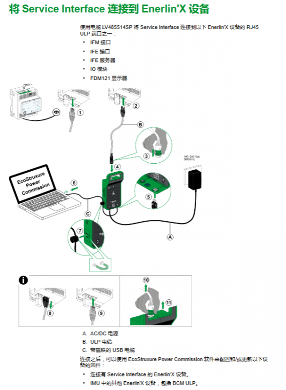
Enerlin’X devices: IO modules, FDM121 displays, IFE/IFM interfaces, etc
Core Value: On site verification of circuit breaker protection function, configuration of equipment parameters, firmware updates, and generation of test reports for acceptance
(2) Safety and compliance requirements
Personnel qualifications: Only qualified electrical personnel are required to perform installation, testing, and maintenance, and must have the ability to operate equipment and identify risks
Network Security: First use must change default password, disable unused ports/services/default accounts, deploy firewalls and network segmentation
Electrical safety: During testing, the circuit breaker may trip, causing downstream power outages, and preventive measures need to be planned in advance; To avoid the risk of arc flash and electric shock, execute the operation after confirming that there is no danger involved
Compliance standards: Complies with IEC 61010-1, IEC 60947-6-2, UL 61010-1 and other standards, with certification covering cULus, CE, etc
Service Interface Hardware and Technical Parameters
(1) Hardware composition and accessories
Specific specifications of component types
Core interface 24Vdc power input port, 24Vdc power output port (120mA), Mini-B USB port, test port, magnetic mount (magnetic installation)
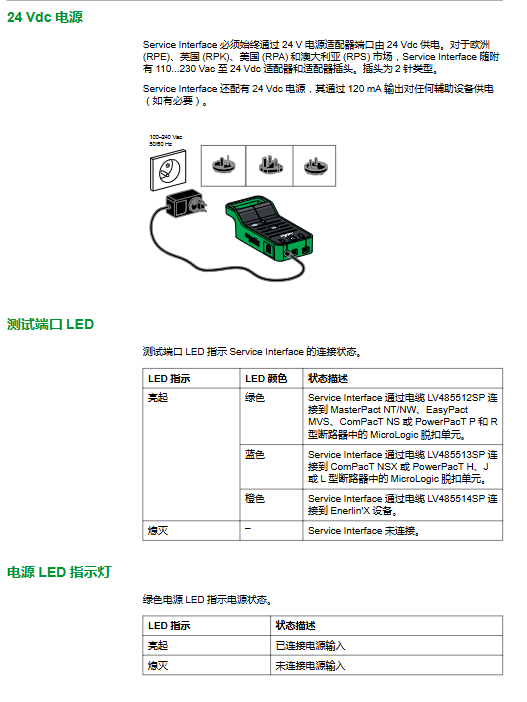
Indicator light power LED (green: powered on), USB LED (green: connected), status LED (orange: boot mode), test port LED (green/blue/orange: corresponding to different device connections)
Special accessory 7-pin cable (LV485512SP: 630-6300A trip unit; LV485513SP: 100-630A trip unit, ULP cable (LV485514SP: Enerlin’X equipment), AC/DC power adapter (110-230Vac to 24Vdc), USB cable with magnet (LV485517SP)
(2) Key technical parameters
Specific numerical values for parameter categories
Electrical parameter input voltage: 24Vdc (-20%~+10%), maximum 525mA
Output voltage: 24Vdc (-20%~+10%), maximum 120mA
Rated power: Service Interface 10W, Adapter 12W
Environmental parameters Operating temperature: -10 ℃~+55 ℃ (14 ° F~+131 ° F)
Storage temperature: -40 ℃~+85 ℃ (-40 ° F~+185 ° F)
Protection level: ULV0 (compliant with IEC/EN 60068-2-30)
Pollution level: Level 3
Mechanical parameters Mechanical impact: Complies with IEC 62262 IK07
Installation methods: wall mounted, countertop, magnetic suction
Core testing functions (classified by circuit breaker type)
(1) MasterPact NT/NW, EasyPact MVS, ComPacT NS, PowerPacT P/R circuit breakers
Compatibility of release unit
The type of trip unit supports testing function
Communication type (such as MicroLogic 2.0A/E, 5.0P/H, 6.0 series) automatic trip curve testing, ZSI testing, forced trip testing, primary injection testing preparation, configuration
Non communication type (such as MicroLogic 2.0/3.0, ET 2. I) automatic trip curve test, forced trip test (without configuration/firmware update function)
Core testing process (taking communication unit as an example)
Connection: Connect the Service Interface to the test port of the trip unit using LV485512SP cable, and connect the 24Vdc power supply
Device discovery: EPC software → Start device discovery → USB/SRIAL → Select device → Enter project information → Connect device
Test execution:
Automatic trip curve test: Select pre configured/custom test points → Enter administrator password → Reset closing circuit breaker → Execute test (can be aborted) → Repeat test → View results
ZSI test: Select upstream devices (≤ 10 units) → Enter password → Run test → Confirm LED flashing status → End test
Forced tripping test: Equipment inspection → Confirm closing → Enter password → Confirm tripping → Generate results
Primary injection preparation: Select test type → Enter password → Suppress thermal memory/ground fault → Manually inject current → Test completed → Restore normal mode
Report generation: EPC software → Report → Project Report → Save/Print
(2) ComPacT NSX, PowerPacT H/J/L circuit breakers
Compatibility of release unit
MicroLogic release unit supports functions
1.2/1.3/2.2/3.2/4.3 series automatic trip curve test, forced trip test, primary injection preparation
5.2/5.3 B/A/E, 6.2/6.3 A/E, 7.2/7.3 E series automatic trip curve testing, ZSI testing, forced trip testing, primary injection preparation, alarm simulation, configuration, firmware update
Featured feature: Alarm simulation
Simulated objects: warning (PAL Ir/IG/I Δ n), 10 user-defined alarms
Verification scenario: FDM121 display (LED flashing/constant, pop-up, alarm history), communication network (Modbus register), SDx module (output status change)
Process: EPC Configuration → Alarm Tab → Select Activate Alarm → Enter Password → Simulate → Verify Results
Enerlin’X device configuration
(1) Compatible devices and functions
Equipment Name Part Number Example Support Function
IO input/output module LV434063 configuration, firmware update
FDM121 Front Display Module TRV00121/STRV00121 Firmware Update
IFE Ethernet interface LV434001 firmware update
IFM Modbus SL interface LV434000 configuration, firmware update
BSCM Circuit Breaker Status Control Module LV434205- (only compatible with connections)
(2) Connection and operation
Connection method: Use ULP cable (LV485514SP) to connect the Service Interface to the RJ45 ULP port of the device
Core operation: EPC software → Configure device parameters (some models), update firmware → Synchronize to other Enerlin’X devices in IMU
Firmware updates and troubleshooting
(1) Firmware update process
EPC software → Connect devices directly → Analyze firmware status → Check Service Interface → Next step
Enter password → click ‘Upgrade’ → wait for completion (cannot be disconnected)
View current/latest firmware version → Close window
Attention: The firmware adopts Schneider digital signature, and the validity of the certificate needs to be checked regularly
(2) Common troubleshooting
Possible causes and solutions for the fault phenomenon
Unrecognized release unit test interval<5 seconds, disconnect → wait for 5 seconds → reconnect
The primary injection test tripped too early, and the suppression function was not disabled before stopping and restarting the suppression function after tripping
Ground fault test without tripping injection current insufficient/MDGF/SGR configuration increases current → Check compatibility → Switch to primary injection test
Automatic tripping test failed (tripping<10ms), closing lock/instantaneous override protection ensures circuit breaker closing → verify protection level