Fault tolerant controller based on Triconex Triple Modular Redundancy (TMR) architecture
The Triconex Tricon system is a fault-tolerant controller based on the Triple Modular Redundancy (TMR) architecture, consisting of a main processor module, I/O module, communication module, power module, and external terminal panel. It supports multiple types of I/O signals such as digital/analog/thermocouple, and has functions such as hot standby replacement, online maintenance, and sequence of events (SOE) recording. The working temperature range is -40 ° C to 75 ° C. It has passed international certifications such as T Ü V, CSA, FM, and is suitable for safety critical industrial scenarios such as emergency shutdown (ESD), boiler flame safety, and turbine control. The maximum system can be expanded to 15 chassis and 118 I/O modules, with a remote I/O distance of 7.5 miles (12 kilometers).
Product basic information
Key project information
Product Name: Triconex Tricon Fault Tolerant Controller System
Core architecture triple module redundancy (TMR), three channel parallel processing+2/3 voting mechanism
Core advantages include no single point of failure, online maintenance, hot standby replacement, and fault self diagnosis
Applicable scenarios include emergency shutdown (ESD), boiler flame safety, turbine control, and offshore fire and gas protection
International certified functional safety: IEC 61508 (SIL 1-3), DIN V 19250; Electrical safety: CSA, FM; Explosion proof: ATEX Zone 2; Nuclear power: NRC Class 1E
Environmental specifications: working temperature -40 ° C~75 ° C, storage temperature -40 ° C~75 ° C; relative humidity 5% -95% (no condensation); Anti vibration 2G (10-150Hz), anti impact 15G (6-11ms)
Core components of the system
(1) Core module type and specifications
Module category, key models, core parameters
Main processor (MP) 3008 16MB DRAM, 32-bit Motorola MPC860 processor, 50MHz
Power modules 8310 (120VAC/VDC), 8311 (24VDC), 8312 (230VAC) 175W (60 ° C), dual redundant design, output 6.5VDC ± 1%
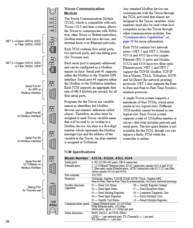
Communication modules TCM (4351A/4352A), EICM (4119A), NCM (4329) TCM: 4 serial ports+2 Ethernet ports; EICM: 4 serial ports+1 parallel port; NCM: 2 Ethernet ports
Digital input (DI) 3501E (115VAC/VDC), 3504E (24/48VDC), 3564 (24VDC) with 32/64 points, response time<2ms~15ms
Digital output (DO) 3601E (115VAC), 3624 (24VDC), 3664 (dual redundancy) points 8/16/32, maximum current 2A/point
Analog input (AI) 3700A (0-5VDC), 3708E (thermocouple) with 16/32/64 points, accuracy<0.15%~0.25% FS
Analog output (AO) 3805E (4-20mA), 3806E (high current) with 8 points (3805E) and 6+2 points (3806E), resolution of 12 bits
Remote Expansion (RXM) 4200-3 (multimode), 4210-3 (single-mode) supports 3 remote sites, up to 12 kilometers away
(2) External terminals and extension components
Terminal panel: including standard type (9561-810, etc.), intrinsic safety type (9572-610, etc.), basic type (9551-110, etc.), supporting 16/32 point signals, including protective components such as fuses and current limiting resistors
Expansion cables: I/O bus cable (9000 series), I/O-COMM bus cable (9001 series), up to 300 meters in length
Auxiliary components: Blank slot panel (8105), heat dissipation baffle (2000361-001), NEMA standard chassis (Rittal/MarkHon series)
System configuration and expansion
Chassis types: main chassis (8110), expansion chassis (8111), remote expansion chassis (8112), dimensions 48.3cm × 57.8cm × 45.1cm, weight 24.5kg
Configuration rules:
The host box must contain 3 3008 main processors, 2 power modules, and provide 6 logical slots
Expansion chassis with up to 8 logical slots, I/O bus distance ≤ 300 meters
Remote chassis needs to be equipped with RXM module, supporting fiber optic transmission, with a maximum distance of 12 kilometers
Maximum size: 15 chassis (1 main+14 expansion/remote), 118 I/O/communication modules
Core functions and software tools
(1) Hardware core functions
Fault tolerance mechanism: Three channel parallel processing, 2/3 voting for digital signals, median for analog signals, single point failure does not affect system operation
Hot standby and maintenance: supports hot standby replacement of I/O modules, online replacement of faulty modules, and the system can run on 1/2/3 main processors
Sequence of Events (SOE): Record changes in discrete variable states with timestamp accuracy of ± 25ms, supporting synchronous acquisition by 31 controllers
Diagnostic function: module level, channel level self diagnosis, fault indicator light+alarm output, supports remote monitoring
(2) Software Tools
Software Name Core Function Compatibility System
TriStation 1131 Control Program Development (LD/FBD/ST Language), Simulation Testing, Download Monitoring Windows NT/2000/XP
CEMPLE Editor Causal Matrix (CEM) programming, automatically converted to FBD code integrated into TriStation 1131
SOE software event data collection, analysis, and export, supporting trip snapshot for Windows system
Enhanced Diagnostic Monitor Multi Controller Hardware/Program Status Monitoring Windows System
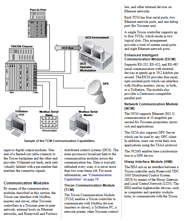
Communication capability
Supported protocols: Modbus (RTU/ASCII/TCP), Ethernet (802.3), Peer to Peer, TSAA, SNTP
Communication interfaces: serial port (RS-232/422/485), Ethernet (RJ-45/fiber optic) Honeywell UCN/LCN、Foxboro Nodebus
Redundant communication: dual communication modules+dual network cables, supporting link/module redundancy
Installation and maintenance
Installation requirements: The chassis should be installed vertically, with a reserved 5.25-inch (13.3cm) heat dissipation space above and below. It is recommended to install a baffle/fan (when the temperature is>50 ° C)
Wiring specifications: The terminal panel supports 24-12AWG cables, with both ends of the shielding layer grounded. The distance between the control cable and the power cable is ≥ 20cm
Maintenance points:
The faulty module can be plugged and unplugged online, and the hot standby module is automatically activated
Dual redundancy of power module, a single module can support the overall load of the machine
Suggest configuring one hot standby module for each type of I/O module and conducting regular module rotation tests