SIEMENS 1FK6 series three-phase servo motor
The full process guide for technical specifications, installation operation, safety specifications, etc. of Siemens 1FK6 series three-phase servo motors (2001 edition, multilingual manual), with IP64 protection level, -15 ℃~+40 ℃ working temperature range, and 20000 hours of bearing life as key parameters, is suitable for driving and positioning equipment such as machine tools and machinery personnel; Siemens SIMATIC S7-300 PLC Beginner’s Guide (2007 edition), taking conveyor motor control as an example, explains in detail the complete process from STEP 7 Lite software installation, CPU 312C hardware wiring to program configuration download. The entire process must comply with electrical safety regulations, and the operation takes about 1 hour.
Core content of 1FK6 series servo motor
1. Basic characteristics of the product
Type: Permanent magnet excitation three-phase synchronous servo motor, compatible with motor controlled AC converter, following the principle of sinusoidal current
Application scenarios: Drive and positioning of machine tools, production equipment, robots, and handling devices
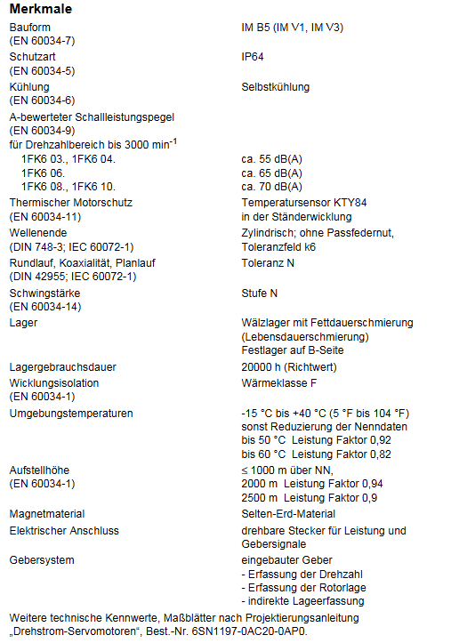
Key parameters:
Protection level: IP64 (basic version), optional IP65/IP67
Working environment: Temperature -15 ℃~+40 ℃ (power coefficient 0.92 at 50 ℃, 0.82 at 60 ℃), altitude ≤ 1000m (coefficient 0.94 at 2000m)
Structural parameters: IM B5/V1/V3 installation form, self cooling, bearing life of 20000 hours
Acoustic characteristics: below 3000rpm, 1FK6 03./04. about 55dB (A), 1FK6 10. about 70dB (A)
2. Key operational procedures
Transportation and Storage:
The weight can reach 50kg and requires suitable lifting equipment to avoid impact
Storage environment: dry, low dust, low vibration (effective vibration<0.2mm/s)
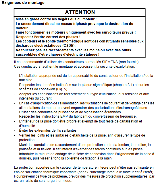
Installation requirements:
Remove the anti-corrosion agent from the shaft end and reserve at least 100mm heat dissipation gap on three sides
Prohibited for use in explosion hazardous areas, motors with integrated brakes are not allowed to withstand axial forces
Bolt strength grade ≥ 8.8, prevent liquid from seeping into the upper bearing when installed vertically
Electrical connection:
Power supply voltage: The terminal voltage can reach 300V when the rotor rotates, and professional personnel are required to operate it
Wiring specifications: Use shielded power and signal wires, comply with EMC requirements, and have a maximum torque of 12Nm (power plug)/20Nm (1FK6 101/103) for the plug
Brake power supply: 24V DC ± 10%, only used for emergency stop, cannot be used as a working brake
Startup and Debugging:
Pre start inspection: Wiring is securely fastened, protective devices are activated, and there is no mechanical jamming
Operating restrictions: The maximum speed must comply with the nameplate markings to avoid overheating (surface temperature ≤ 140 ℃)
3. Safety and Maintenance
Safety regulations:
Anti electric shock: Operate the electrical part after power failure, following EN 50110-1 standard
Thermal injury prevention: Avoid touching high-temperature surfaces and keep temperature sensitive components away from heat sources
Anti magnetic interference: Pacemaker wearers should stay away from disassembled rotors, and electronic data media should be kept away from them
Maintenance and disposal:
Routine maintenance: Clean according to the degree of pollution to ensure smooth heat dissipation
Troubleshooting: Identify issues through vibration, noise, and temperature anomalies (such as vibration requiring rebalancing and overheating requiring load inspection)
Scrap disposal: Follow local regulations and dispose of encoder electronic components as electronic waste
SIMATIC S7-300 PLC Beginner’s Guide Core Content
1. Pre preparation
Skill requirements: Proficient in operating Microsoft Windows and mastering basic knowledge of electronics and electrical engineering
Material List (Core):
Hardware: CPU 312C, power module (6ES7307-1EA00-0AA0), installation track, 4 24V momentary contact switches PC Adapter USB
Software: STEP 7 Lite V3.0+SP2 (free download), PC Adapter USB driver
Tools: M6 screw, wire stripping pliers, crimping tool, 3.5mm/4.5mm blade screwdriver
2. Core operating procedures
Step 1: PC Preparation
Install STEP 7 Lite software and PC Adapter USB driver
Configure PG/PC interface: Select “PC Adapter (MPI)” and establish a communication connection between USB and CPU
Step 2: Hardware installation and wiring
Installation track: fixed and grounded (cross-sectional area of grounding cable ≥ 10mm ²), with a gap of ≥ 40mm reserved above and below
Module installation: Install the power supply in sequence CPU 312C, Insert the front connector (for easy wiring)
Wiring rules:
Signal transmitter (momentary contact switch) connected to CPU digital input terminal (DI)
Signal receiver (motor) connected to CPU digital output terminal (DO)
Cut off the power before wiring to avoid voltage hazards
Hardware debugging: After powering on, press the switch to test whether the CPU input LED lights up normally
Step 3: Software Configuration and Programming
Project operation: Open the “conver. k7p” instance project, create S7-300 station, configure power supply and CPU module
CPU parameter setting: Set the reserved bit storage quantity to “0” to avoid motor loss of control after power failure
Online connection: Establish MPI communication between PC and CPU, download configuration and verify consistency
Program view: Open the OB1 organization block, and the program is presented in ladder logic (LAD), including 4 control networks (start stop/reverse)
Step 4: Test Run
Project Download: Download the hardware configuration and program together to CPU 312C
Operation: Turn the CPU mode switch to “RUN”, start with the green switch, stop with the red switch, and control the direction change with the switches on both sides
Status verification: Observe whether the CPU output LED is consistent with the motor action
3. Auxiliary information
Error diagnosis:
PLC malfunction: troubleshooting through CPU SF (error) LED and PC Adapter LED
Reference documents: “S7-300, CPU 31xC and CPU 31x: Installation” and “PC Adapter USB” electronic manual