ABB SACO 16D1 Annunciator unit
ABB SACO 16D1 is an independent multi-channel alarm annunitor unit based on a microprocessor, with 16 alarm input channels, 4 auxiliary output relays, supporting on-site contact (NO/NC type) access and pulse counting function, equipped with first out alarm indication, 50 event records and serial communication interface (SPA bus), which can be programmed through the front panel buttons or serial port. It has complete self checking function and IP54 protection level, and is widely used in power plants, substations, industrial processes, ships and water treatment plants, etc. It can achieve visual/auditory alarm, event recording and remote monitoring of abnormal working conditions.
Product basic information
Product positioning
ABB SACO 16D1 is an independent microprocessor multi-channel alarm annunitor unit, which is part of the SPACOM substation secondary equipment system.
It can be used independently or integrated into the system as a data acquisition, recording, or control unit.
Core parameters
Project specifications
16 input channels, supporting NO/NC contacts and pulse counting
There are 4 output relays, 2 of which can be configured with flash groups, 1 auditory device, and 1 self check
Event recording capacity: 9 local records and 50 serial records (with timestamp and resolution of 5ms)
Power supply range SPGU 240A1: 80-265V AC/DC; SPGU 48B2:18-80V DC
Protection level IP54 (during panel installation)
Communication interface RS485 (SPA bus), optional speed range of 300-9600bps
Pulse counting range 0-29999, maximum frequency 3Hz
Core functions
Alarm input and processing
Channel type: Supports 7 input signal types, including NO/NC contacts, rising/falling edge triggering, and pulse counting (contact closure/disconnection/bidirectional counting).
Delay setting: Both input delay and reset delay can be programmed and selected, ranging from 5ms-160s, and can also be customized through serial port.
Pulse counting: The counter has no battery backup and will reset to zero after power failure; The count value can be read/set through SPA bus parameter V5.
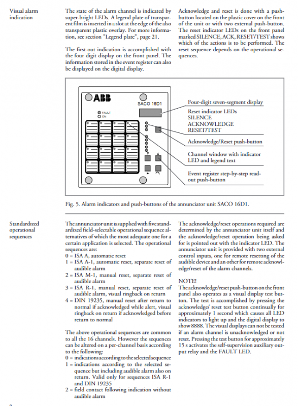
Alarm indication and operation
First alarm: The first triggered alarm channel is displayed on the 4-digit screen with an A+channel number, which can be reset by pressing the button.
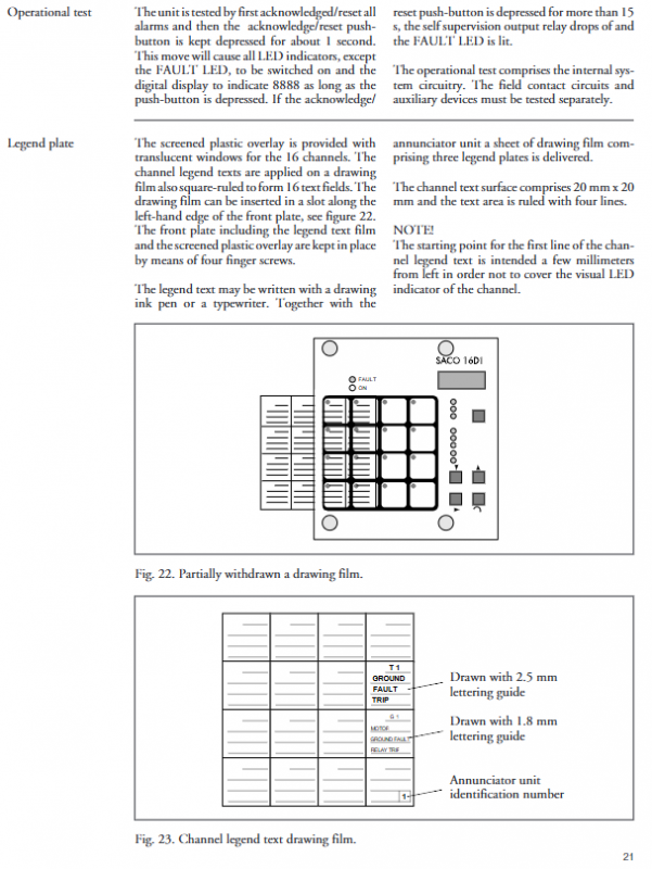
Visual alarm: Each channel is equipped with high brightness LED and supports 5 standardized operation sequences (such as ISA A automatic reset, DIN 19235 manual reset).
Auditory alarm: The buzzer/horn is controlled by a dedicated relay and can be muted through panel buttons or remote input.
Event log
The local event register stores 9 latest events, which can be read one by one through panel buttons; The serial event register stores 50 timestamp events and supports uploading to the higher-level system.
Event types include alarm triggering, alarm disappearance, confirmation operation, etc.
interlocking function
Each channel is equipped with 3 interlocking inputs and 1 interlocking output, supporting 8-level interlocking configuration.
Interlocking types include: blocking flashing signal A, blocking the entire channel (confirmed alarm after reset), and blocking the entire channel (new alarm after reset).
Exceeding level 3 interlocking will affect the resolution of event timestamps.
Self checking function
Continuously monitor internal voltage, program execution, and microprocessor logic. When a fault occurs, the FAULT LED lights up and the self-test relay activates.
Support on-site contact voltage monitoring, and fault information can be uploaded through the serial port.
Programming and Communication
programming method
Local programming: Set parameters through the 5 buttons on the front panel, which are stored in non-volatile EEPROM.
Remote programming: Connect to a PC via serial port and configure using SMS 010 software.
Programming protection: Lock parameters through the selection plug on the PCB to prevent unauthorized modifications.
communication function
Supports SPA bus protocol and can be connected to data collectors such as SRIO 500M/1000M.
The LED flashing sequence of multiple devices can be synchronized, supporting fiber optic communication modules (transmission distance of plastic fiber optic 30m, glass fiber optic 2km).
Installation and maintenance
install
Embedded panel installation, optional 40/80/120mm extension frame to reduce the depth behind the panel.
The terminal block supports wires up to 2.5mm ² without the need for a wire nose, and comes with a wiring diagram on the side.
maintenance
The module is designed to be plug-in, and the parameter memory (D17) of the old module can be reused during replacement.
Under normal working conditions, maintenance is basically free. In harsh environments, regular inspections are required for mechanical damage, oxidation, and dust accumulation.
Application scenarios
Suitable for scenarios with high requirements for reliability and anti-interference, including power plants/substations, industrial processes, ships and offshore platforms, building technology facilities, water treatment plants, etc.