Reliance Electric Engineering Drive System and DBU Dynamic Braking Unit
The Reliance Electric engineering drive system and DBU dynamic braking unit are a complete solution for industrial motor control. The core includes the installation and operation specifications of the engineering drive system and the DBU-50/100/200/400 dynamic braking unit (37-300kW power). The system must comply with mechanical installation (space/environment/lifting) and electrical compliance (wiring classification/grounding/overcurrent protection) specifications. The DBU unit converts DC bus electrical energy into thermal energy through PWM regulation to achieve rapid braking. It supports 415V/460V line voltage switching and BUD diagnostic function, and needs to be used with braking resistors. It is suitable for industrial scenarios with high inertia/active loads as a whole. Installation and operation must strictly comply with safety and EMC standards.
Overall specification for engineering drive system
Equipment reception and identification
Receiving inspection: After arrival, the packaging needs to be checked for integrity, and any damage needs to be marked on the carrier’s documents and inspected.
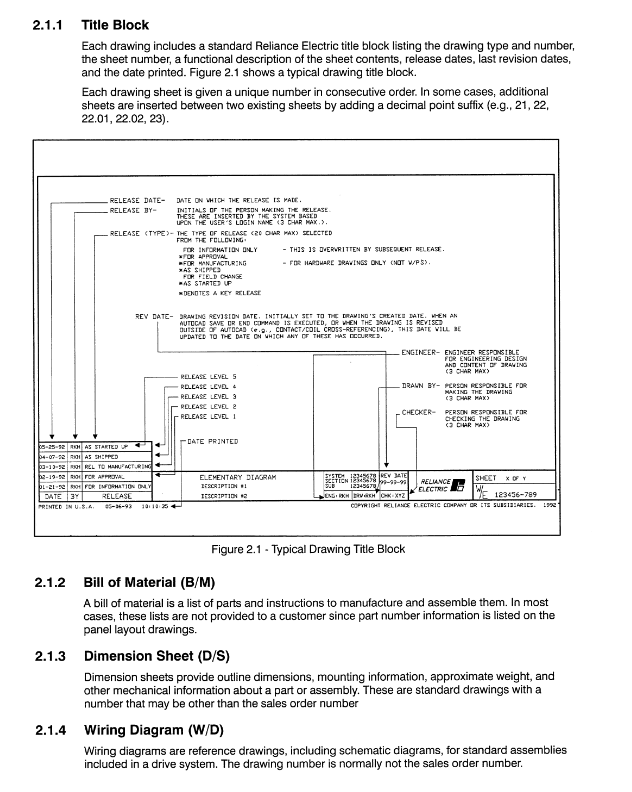
Equipment identification: Each device contains a unique serial number (including order number/sub order prefix/quantity suffix), production date code, and nameplate indicating core parameters such as voltage/current/power.
Document requirements: The accompanying Instruction Book should include a list of equipment, drawings, manuals, and spare parts, and be updated and revised after startup.
Mechanical installation requirements
Space and spacing (key numbers):
Equipment type Front spacing Top spacing End spacing
Wall mounted operation cabinet -10 inches (254mm)-
Floor console 36 inches (914mm) 18 inches (457mm)-
Mill Control Class A -48 inches (1219mm)-
Environmental restrictions: Operating temperature is 0-40 ℃ (with a 1.5% reduction in capacity per ℃ between 40-55 ℃), storage temperature is -25-55 ℃, avoiding corrosive, dusty, and vibrating environments.
Lifting specifications: Use the equipment with its own lifting ears, with a sling angle of ≥ 45 °. For heavy equipment, spread bars are required to avoid pulling or pulling the wiring terminals.
Electrical installation compliance
Wiring Classification (IEEE Standard):
Level 1 (low-level signal):<50V analog signal, 4-20mA signal, requires shielded cable, with a distance of 26 inches from the power line.
Level 4 (power circuit):>20A/250V AC/DC, independent conduit, with a distance of ≥ 26 inches from Level 1.
Core protection:
Overcurrent protection: Branch circuits need to be matched with fuses/circuit breakers, with specifications configured according to 115% of the rated current of the equipment.
Grounding requirements: The metal casing of the equipment should be grounded, and the cross-sectional area of the grounding conductor should be ≥ 16mm ² or 50% of the phase line.
Disconnecting device: visible and lockable within 50 feet of the equipment.
Cable specifications:
Fiber optic cable: 62.5/50 micron duplex, maximum 750 meters, bending radius ≥ 10 times the diameter.
Shielded cable: 360 ° grounding, used for signal and power cable isolation.
DBU dynamic braking unit details
Core parameter table
|Model | Maximum braking current | Continuous braking power (460V) | Minimum resistance (460V) | Weight|
| DBU-50 | 50A | 9kW | 14.4Ω | 3.1kg |
| DBU-100 | 100A | 18kW | 7.2Ω | 3.1kg |
| DBU-200 | 200A | 36kW | 3.6Ω | 9kg |
| DBU-400 | 400A | 72kW | 1.8Ω | 10kg |
Voltage switching: Select 415V (starting voltage DC 680V) or 460V (starting voltage DC 750V) through the blue jumper, default 460V.
Load limit: Maximum current allowed to run for 2.5 minutes within 10 minutes (DBU-400 is 400A x 110 seconds).
Installation and Wiring
Installation requirements: Vertically fixed on the metal panel, with a 100mm heat dissipation gap reserved above and below; DBU-400 requires forced ventilation (158m ³/h).
Short circuit protection: Series aR type fuses (50A for DBU-50 and 400A for DBU-400) are used to prevent IGBT short circuit faults.
Cable requirements:
Inverter DBU: Line length ≤ 1.5m, shielded cable bundled and laid to reduce inductance overvoltage (≤ 200V).
DBU – Resistance: High temperature resistant cable to 90 ℃, τ=L/R<20μs, Cross section matching (DBU-400 uses 95mm ²).
Diagnosis and Design Calculation
BUD diagnostic card function:
Indicator lights: left LED (DC bus>50V), right LED (braking current>0).
Output signals: switch output (monitoring braking status), analog output (0-20mA feedback braking power).
Key calculation formula:
Braking power:
P [kW]=91200 ⋅ t B J ⋅ Δ n ⋅ n (J=moment of inertia, n=pre braking speed).
Braking resistor: at 415V
At R=439/P and 460V
R=534/P, Must be ≥ minimum resistance value.
Example: A roller conveyor with 20 2.5kW motors, braking time of 1.8s, requires 50kW braking power, and DBU-100 and 10 Ω resistors are selected.
Service and Operations Support
Startup and Debugging Services
Service scope: equipment inspection, control logic verification, static/dynamic parameter adjustment, load testing.
Purchase method: By hour/prepaid days/fixed price, a pre launch meeting must be held one month in advance to confirm the plan.
Subsequent operation and maintenance support
Fault service: 24/7 telephone consultation, on-site maintenance, vibration analysis, power system testing.
Spare parts supply: Global inventory center, providing spare parts list and recommended inventory quantity, supporting emergency delivery.
Training services: Cleveland headquarters courses, regional courses, in-house customized training, including video tutorials and practical guidance.