RELIANCE ELECTRIC GV3000/SE AC Drive (Version 6.06)
The GV3000/SE AC drive (Version 6.06) is a universal AC drive that supports V/Hz regulation and vector regulation (FVC/SVC). It has core functions such as keyboard/display operation, multi parameter programming, and fault diagnosis. It can be adapted to different application scenarios by setting universal parameters (P series), V/Hz parameters (H series), or vector parameters (U series). It supports local/remote control, built-in alarm and fault handling mechanisms, and is widely used in industrial motor speed control. It must strictly follow safety regulations and startup processes to ensure stable operation.
Product Overview
Basic Information
Model: GV3000/SE AC Drive, software version 6.06
Core positioning: Universal motor speed control driver, supporting two adjustment modes, suitable for industrial general scenarios
Control Scalability: Supports local keyboard, terminal block, network (DeviceNet/ControlNet, etc.), serial port (CS3000 software/OIM module) control
Core Features
Adjustment modes: V/Hz adjustment (open-loop, default), vector adjustment (closed-loop, including FVC requiring encoder, SVC without encoder)
Monitoring function: It can display six types of operating data, including speed, voltage, current, frequency, power, and torque (vector only)
Protection functions: 30+fault protections including motor overload protection, overcurrent protection, overvoltage protection, encoder loss protection, etc
Programming flexibility: Parameters are divided into two levels of menus, support password protection, and parameter values are retained in case of power failure
Detailed explanation of the startup process
Key steps of core preparation work for adjustment mode (simplified) Core parameter configuration
V/Hz adjustment 1. Complete hardware installation (power supply, motor wiring)
2. Record the motor nameplate parameters (rated voltage/current/fundamental frequency)
3. Confirm that programming has not been disabled (P.051) 1. Power on self-test (displaying SELF)
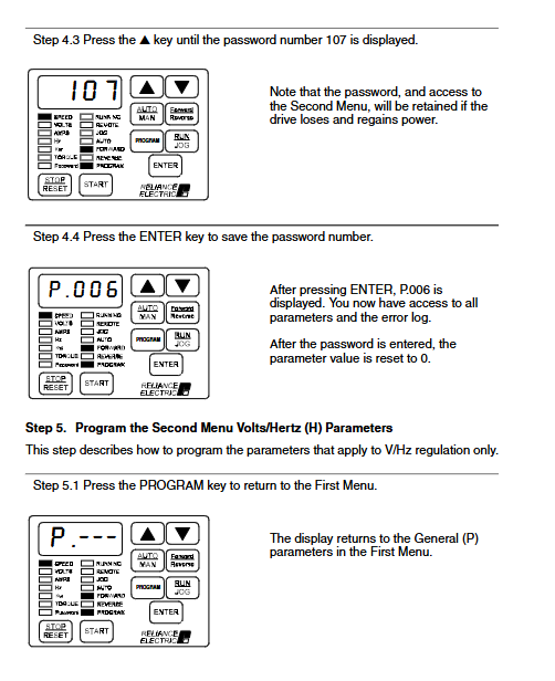
2. Enter program mode configuration P.000-P.005 (control source, acceleration/deceleration time, etc.)
3. Enter password 107 (P.006) to unlock the second menu
4. Configure H-series parameters (motor nameplate, torque boost, etc.)
5. Verify motor steering → Test run P.000 (LOCL local control), P.001-P.002 (default for 20.0 seconds), H.000 (motor voltage), H.003 (default for torque increase of 0.5%)
Vector adjustment 1. Complete hardware installation (including encoder wiring, FVC mode)
2. Record motor/encoder parameters (pole count, PPR, etc.)
3. Disconnect the motor load. 1. Power on self-test → Enter program mode
2. Enter password 107 → switch adjustment mode (P.048=UEC)
3. Configure P/U series parameters (speed limit, motor nameplate, etc.)
4. Perform self-tuning (U.008=ON) → Verify steering
5. Connect the load → Test run P.003 (default 150 RPM), U.001 (default 1024 PPR), U.002 (default 4-pole), U.017 (maximum motor speed)
Keyboard and Display Operations
Operation Mode
Monitoring mode (default): Press ENTER to switch display data, supports manual input of speed reference
Program mode: Press the Program key to enter, used for parameter configuration and error log query
Keyboard key function
Core buttons: AUTO/MAN (switch between automatic/manual reference source), GRAM (mode switch), START/STOP/RESET (start stop/reset)
Adjustment buttons: ↑ (increase value), ↓ (decrease value), ENTER (confirm/save)
LED indicator
Status LEDs (8): Running, Remote Control, Program Mode, etc
Monitoring LEDs (6): SPEED (speed), VOLTS (voltage), AMPS (current), etc., corresponding to display data types
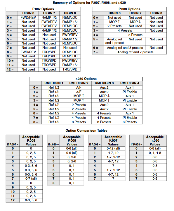
Detailed Explanation of Parameter System
Parameter classification and access
First menu (P.000-P.006): Basic general parameters, no password required, including control source, acceleration/deceleration time, current limit, etc
Second menu: Password 107 (P.006) is required to access, including extended general parameters, V/Hz specific parameters, vector specific parameters, and RMI board parameters
Parameter types: configurable (only for shutdown modification), adjustable (can run/shut down), read-only (such as software version P.098)
Key parameter description
General core parameters
Parameter number, parameter name, function, adjustment range (V/Hz), adjustment range (vector), default value
P. 000 Control Source Select Control Source – LOCL (Local)
P. 001 Accel Time 1 Acceleration Time 1.0-999.9 seconds 0.1-999.9 seconds 20.0 seconds
P. 003 Minimum Speed Minimum Speed 0.5-Hz (P.004) 0-RPM (P.004) 5.0Hz 150RPM
P. 005 Current Limit 50-110% U.006-150% 100% 150%
P. 051 Programming Disable programming lock 0-9999 (password 26) -0 (unlocked)
V/Hz exclusive parameters
Parameter number, parameter name, function, adjustment range, default value
H. 000 Motor Nameplate Volts Motor rated voltage 100-690VAC 460VAC
H. 003 Torque Boost Voltage Low Speed Torque Boost 0.0-20.0% 0.5%
H. 009 Avoidance Frequency Enable ON/OFF
H. 022 Overfrequency Limit Overfrequency protection threshold 30.0-210Hz 90.0Hz
Vector specific parameters
Parameter number, parameter name, function, adjustment range, default value
U. 001 Encoder PPR Encoder Pulse Count 512/1024/2048/4096/SE 1024
U. 002 Motor Poles Motor Pole 2/4/6/8 4
U. 008 Torque Self Tune Enable self-tuning enable ON/OFF OFF
U. 012 Speed Regulator Proportional Gain Speed Proportional Gain 0.01-99.99 Module Dependence
Fault and alarm handling
alarm mechanism
Definition: Non fatal exception, drive continues to run, flashing alarm code displayed
Common alarms: 7 categories including AIn (loss of analog input signal), LIL (low input voltage), S-En (self-tuning enabled), etc
Solution: Investigate the cause of the abnormality (such as signal lines, input voltage), no need to reset, automatically clear after the abnormality is resolved
Fault mechanism
Definition: Fatal exception, immediate shutdown of the drive (free parking or slope parking), flashing display of fault code
Common faults: OC (overcurrent), OL (motor overload), OH (driver overheating), OSP (overspeed), EL (encoder loss), etc
Error log: Automatically stores 10 latest faults, including date (0-248 days) and timestamp (24-hour format), supports manual clearing
Fault reset method
Local reset: Press the STOP/RESET key on the keyboard
Remote reset: sending a fault reset signal through the control source
Attention: It is necessary to first investigate the cause of the fault (such as short circuit, overload), otherwise resetting may trigger the fault again
Safety regulations
Electrical safety
Anti electric shock: There is dangerous voltage inside the equipment, and non professionals are prohibited from opening the cover
Arc flash protection: Suitable personal protective equipment (PPE) must be worn
Capacitor discharge: After power failure, wait for 5 minutes to confirm that the DC bus capacitor discharge is complete before contacting internal components
Mechanical safety
Rotating components: When the motor is running, the rotating shaft should be protected to avoid contact
Zero speed warning: The drive supports zero speed operation and requires warning devices (such as indicator lights and alarms) to be installed
Direction verification: The motor direction must be verified during the first start-up, and if there is an error, the two-phase wiring of the motor needs to be swapped
Operational Security
Password management: The second menu password (107) and programming lock password (26) should be properly kept to prevent unauthorized modification
Emergency shutdown: An external hard wired emergency shutdown circuit must be configured to ensure rapid shutdown in case of abnormalities
Parameter verification: After modifying key parameters such as speed limit and current limit, a trial run is required to verify stability