RELIANCE ELECTRIC INVERTRON DBU Dynamic Braking Unit
The Reliance Electronics INVERTRON DBU dynamic braking unit is a core component adapted for frequency converters such as GV3000, INVERTRON VTI/VCI/VGI, etc. It converts DC bus electrical energy into thermal energy to achieve rapid motor braking, avoiding bus overvoltage tripping, providing 37kW-300kW power specifications (DBU-50/100/200/400 models), supporting 415V/460V line voltage switching, built-in PWM type regulator (BUC) and optional diagnostic card (BUD), and needs to be used with braking resistors. Installation must comply with EMC specifications and heat dissipation requirements, and is widely used in industrial scenarios such as high inertia loads (centrifuges) and active loads (cranes).
Product Overview
Core positioning and role
Product definition: Dynamic Braking Unit (DBU) is a component of a frequency converter used to consume excess electrical energy from the DC bus during rapid motor braking, avoiding bus overvoltage tripping (such as HU fault in GV3000).
Working principle: The DC bus electrical energy is introduced into the braking resistor through IGBT switches, converted into thermal energy for dissipation, and supports motor braking in more than 2 quadrants (conventional frequency converters only support electric operation in 2 quadrants).
Model classification: 4 core models, classified by power. DBU-400 comes with a built-in diagnostic card (BUD) by default, while other models can be equipped with the DBU-DIS kit.
Key model parameter table | Model | Maximum braking current (Imax) | Continuous braking power (460V) | Short time braking power (460V) | Minimum braking resistance (460V) | Weight|
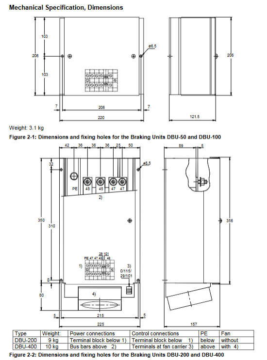
| DBU-50 | 50A | 9kW | 37.5kW | 14.4Ω | 3.1kg |
| DBU-100 | 100A | 18kW | 75kW | 7.2Ω | 3.1kg |
| DBU-200 | 200A | 36kW | 150kW | 3.6Ω | 9kg |
| DBU-400 | 400A | 72kW | 300kW | 1.8Ω | 10kg |
Note: Under 415V line voltage, the minimum resistance and short-term power are slightly lower (such as DBU-50: 12.8 Ω, 34kW).
Installation specifications
Installation requirements
Installation method: Vertically fixed on the metal panel, with the cooling fins facing upwards and a 100mm heat dissipation gap reserved above and below.
Environmental restrictions: Working temperature 0-40 ℃, rated current decreases by 1.5% per ℃ at 40-55 ℃; Storage temperature -25-55 ℃, transportation temperature -25-70 ℃ (maximum 24 hours).
Forced ventilation: DBU-400 requires forced ventilation with an air volume of 158m ³/h and airflow direction from bottom to top.
Protection and wiring
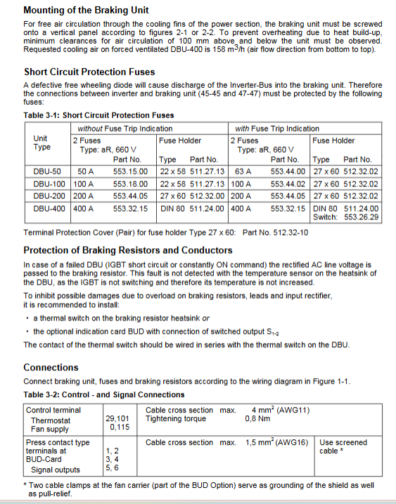
Short circuit protection: aR type fuses need to be connected in series between the frequency converter and DBU, with specifications as shown in the table below:
|Model | No trip indication fuse | With trip indication fuse | Fuse holder model|
| DBU-50 | 50A(553.15.00) | 63A(553.44.00) | 22×58(511.27.13) |
| DBU-100 | 100A(553.18.00) | 100A(553.44.02) | 22×58(511.27.13) |
| DBU-200 | 200A(553.44.05) | 200A(553.44.05) | 27×60(512.32.02) |
| DBU-400 | 400A(553.32.15) | 400A(553.32.15) | DIN 80(511.24.00) |
Resistance protection: The braking resistor needs to be equipped with a thermal switch and connected in series with the DBU thermal switch to prevent the resistor from being overloaded and burned out.
Wiring specifications:
Inverter DBU: wire length ≤ 1.5m, shielded cable bundled and laid to reduce inductance; When multiple frequency converters share the same bus, the DBU needs to be close to the maximum capacitor group.
DBU – Resistance: Use cables that can withstand high temperatures above 90 ℃, with a wire length of τ=L/R<20 μ s, and a cable cross-section that matches the model (DBU-400 requires 95mm ²).
Grounding: The PE terminal is reliably grounded, the shielding layer is grounded 360 °, and the grounding resistance meets EMC requirements.
Function and Diagnosis
core functionality
Voltage switching: Select the 415V/460V line voltage through the blue jumper, corresponding to the braking starting voltage DC 680V/750V, default 460V.
Adjustment method: PWM type regulator (BUC) is used, with a switching frequency of 1kHz, and the braking current is controlled by pulse width.
Load limit: Allow maximum braking current to run for 2.5 minutes within 10 minutes (DBU-400 runs at 400A for 110 seconds) to avoid IGBT thermal overload.
Diagnostic Card (BUD) Function
Status indication:
Left LED: When the DC bus voltage is greater than 50V, it lights up, indicating that the bus is live.
Right LED: It lights up when the braking current is greater than 0, indicating that the braking is in progress.
Switch output (S1-2): 24V/20mA transistor switch, closed when bus>50V and no braking, disconnected during braking or bus<50V, used to monitor braking status.
Analog output (A5-6): 0-20mA signal feedback braking power, 0% corresponds to 0mA (no braking), 100% corresponds to 20mA (maximum braking power), requires external 24V power supply.
Design Calculation
Braking power calculation
Formula:
P[kW]= 91200⋅t B J⋅Δn⋅n
Parameter description: J (system moment of inertia, kg · m ²), n (pre braking speed, min ⁻¹), Δ n (speed change, min ⁻¹), t_B (braking time, s)。
Example: A roller conveyor with 20 2.5kW motors, braking time of 1.8s, total power of 50kW, requires the selection of DBU-100 (75kW).
Braking resistance calculation
415V line voltage: R [Ω]=P [kW] 439
460V line voltage: R [Ω]=P [kW] 534
Requirement: Resistance value ≥ minimum resistance (to avoid current exceeding the standard), time constant τ=L/R<20 μ s (to prevent IGBT overvoltage).
EMC compliance requirements
Installation compliance
Faraday cage: all drive components (frequency converter, RFI filter DBU、 The resistor needs to be installed in a metal cabinet or independent metal shell, with a ventilation hole diameter of ≤ 6mm.
Grounding: The PE wires between the equipment are continuously connected, and the grounding busbar is well conductive with the cabinet. The shielded cable is grounded through the EMC test cable gland.
Wiring compliance
The power line and signal line are laid separately, the signal cable uses shielded wire, and the motor cable uses 4-core shielded wire (3-phase+PE).
External wiring requires the use of metal conduits or shielded cables, with both ends of the shielding layer grounded.