KOLLMORGEN digifas ™ 7200 series digital servo amplifier
KOLLMORGEN digifas ™ The installation and operation guide for the 7200 series digital servo amplifier (including models 7201/7204/7206, etc.) is designed to adapt to three-phase 400V industrial power supply and provide speed/torque control for 6SM series brushless synchronous servo motors. It supports ± 10V analog setpoint input, incremental encoder/SSI interface feedback, peak output current up to 12A, working temperature * * -25 ° C to+55 ° C * * (power derating required), protection level IP20, EMC compliant design, energy feedback braking (ballast circuit), and complete fault protection. It is equipped with BS7200 software to achieve parameter configuration and monitoring. The manual covers the entire process of installation, wiring, debugging, fault troubleshooting, etc., and is suitable for multi axis industrial motion control scenarios.
Product basic information
Product positioning and series differentiation
Core attribute: Digital servo amplifier, designed specifically for 6SM series brushless synchronous servo motors, only suitable for three-phase 400V industrial grounding power supply, providing speed/torque control, no built-in position control (needs to be extended through CONNECT module)
Model difference: Classified by output current, key parameters are shown in the following table:
|Model | Continuous output (S1 mode) | Peak output current | Power of ballast resistor | Applicable motor power|
|7201 | 0.9kVA | 3.0A | 75W | Low Power 6SM Series|
|7204 | 1.7kVA | 8.4A | 75W | Medium Power 6SM Series|
|7206 | 2.5kVA | 12A | 140W (requires BV forced cooling) | High power 6SM series|
Extended version: Supports BIT/CAN/PROFIBUS/PULSE CONNECT modules to achieve functions such as PLC, bus communication, pulse commands, etc; Optional – IL module achieves controllable torque limitation
Core hardware and environmental specifications | Specification categories | Key parameters|
|Power supply and output | Voltage: three-phase 400VAC (± 10%), frequency 47-60Hz; intermediate circuit voltage 560VDC, overvoltage threshold 750VDC|
|Control signal | Analog set value: ± 10V (14 bit resolution, input impedance 20k Ω); Digital I/O: 24V (PLC compatible)|
|Feedback Interface | Incremental Encoder (ROD): 500/512/1000/1024 pulses per revolution; SSI interface: maximum 1.5MHz clock|
|Physical dimensions | Standard model: 275 × 71 × 235mm; with BV cooling: 310 × 73 × 236mm|
|Environmental adaptability | Operating temperature: -25 ° C~+55 ° C (power reduction of 2.5% for every 1K increase above 45 ° C); Humidity 5% -85%, no condensation|
|Protection and insulation | Protection level IP20, compliant with VDE 0160 insulation standard, creepage distance meets EN 50178|
Installation and wiring specifications
Installation requirements
Installation location: It must be installed inside a closed switchgear to avoid conductive/corrosive environments, and installed vertically to ensure natural heat dissipation
Cooling distance: Adequate space should be reserved above and below the amplifier (refer to installation diagram V.7). If the ballast power of 7206 model is greater than 75W, BV forced cooling should be configured
Grounding requirements: The installation board needs to be grounded, and the amplifier is grounded in a single point star shape through a grounding bolt (M6). The cross-section of the grounding wire should be ≥ 10mm ²
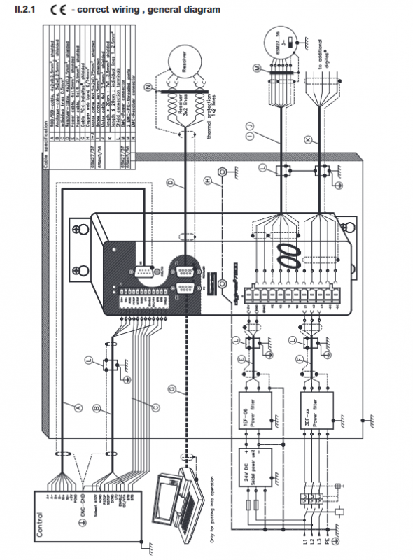
Core wiring specifications
Cable separation: The distance between the power line (power supply, motor line) and the signal line (set value, feedback line) is ≥ 20cm, and they intersect at a 90 ° angle
Cable specifications:
Motor wire: Use 1.5-2.5mm ² shielded wire for ≤ 25m; 25m with 4 × 1mm ² shielded wire and 3YL-06 choke box
Feedback line: Resolver/ROD/SSI wire with twisted pair shielded wire (0.25mm ²), up to 100m in length
Shielding treatment: All shielded cables must be grounded at both ends and connected with low impedance through shielding clips or metal joints
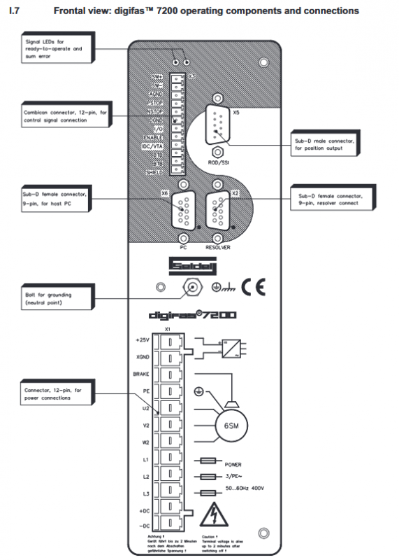
Key interfaces:
Power interface (L1/L2/L3): 3EFxx series filters need to be configured, and the user needs to provide a circuit breaker with phase loss monitoring
Auxiliary power supply: 25VDC (compatible with 18-36V), requires 1EF06 filter, maximum output current 2A (with brake)
Motor interface (U2/V2/W2): including brake wiring (BRAKE), brake voltage 24VDC ± 10%
EMC Compliance Configuration
Specific filters must be configured: 1EF06 for auxiliary power supply and 3EFxx series for main power supply
When the motor cable is greater than 25m, it is mandatory to use 3YL-06 choke box to suppress capacitive reactive current
All control signals must use shielded wires, and the shielding layer should be well grounded to the switchgear
Software configuration and debugging
BS7200 software functions
Operating environment: MS-DOS 3.3+, CPU above 80386, 1MB memory, VGA graphics card
Core functions: parameter configuration, real-time monitoring (current/speed/temperature), fault diagnosis, service mode (constant speed/constant current/reverse)
Connection method: Connect the PC parallel port or serial port (requires a power adapter) through a 9-core dedicated cable
Key parameter configuration
Motor parameters: number of motor poles (2-12 poles), number of resolver poles (2/4/6), to be matched with 6SM motor
Current control: Irms (continuous current, maximum motor rated current), Ipeak (peak current, maximum 4 × Irms), Kp (proportional gain 0.1-8), Tn (integration time 0.1-10ms)
Speed control: Kp (proportional gain 1-61), Tn (integration time 0.1-9999ms), SW ramp (set value ramp 2-8000ms), speed limit (800-6000rpm)
Interface parameters: ROD/SSI selection, resolution setting, NI offset (zero pulse position)
debugging process
Power off inspection: wiring correctness, grounding continuity, motor and amplifier parameter matching
Power on preparation: First, turn on the 25VDC auxiliary power supply, and the green LED will light up (initialization takes about 0.5 seconds)
Software connection: Start BS7200, read and verify parameters (motor pole number, current limit, speed limit)
Enable test: Set the value to 0V, enable the amplifier (X3/16 terminal 24V), and the motor is in the braking state
Run test: Input 0.5V simulated set value (or start service mode), observe motor operation status, optimize gain parameters
Multi axis debugging: Multi axis systems require separate debugging of each amplifier, and when sharing intermediate circuits, unified ballast parameters are required
System functions and protection
Core control function
Double loop control: current loop (update rate 8.33kHz), speed loop (including PID regulation), supporting phase compensation (0-45 ° electrical angle)
Set value processing: Supports ± 10V differential input, built-in offset compensation, slope adjustment (2-8000ms)
Energy feedback: The braking energy is converted into heat through the ballast resistor, and multiple axes can be connected in parallel to share the ballast capacity with the intermediate circuit
Monitoring output: Analog output (X3/23) can choose between current (IDC, 8-bit resolution) or speed (VTA, 10 bit resolution) monitoring
protection function
Fault types: including undervoltage (65VDC threshold), overvoltage (750VDC threshold), overcurrent, output stage fault, overheating (heat sink 80 ° C/internal 70 ° C), motor overheating (145 ° C), braking fault, resolver fault, grounding fault, etc
Fault response: All faults trigger the red LED to light up, BTB relay to disconnect, output stage to shut down, requiring reset enable or power-off restart
Other protections: I ² t current monitoring (to prevent overload), limit switch protection (PSTOP/NSTOP, can set stop/disable direction)
Troubleshooting and Maintenance
Common fault handling | Fault signal | Possible causes | Troubleshooting measures|
|Overvoltage | Excessive braking energy, insufficient ballast power | Increase ballast power parameters, shorten braking ramp, parallel intermediate circuit|
|Output level fault | Motor line short circuit/grounding, output level overheating | Check motor cable, improve heat dissipation, return to factory for repair|
|Resolver malfunction | Loose wiring, cable breakage, model mismatch | Check the Resolver cable and confirm 2/4/6 pole pairs match|
|Motor not turning | not enabled, set value circuit broken, motor phase missing | Check ENABLE signal, set value cable, motor phase wiring|
|Motor oscillation | High speed loop gain, poor shielding | Reduce Kp parameter, replace shielding cable, ensure AGND grounding|
Maintenance and Storage
Daily maintenance: Maintenance free design, the outer shell can be wiped clean with isopropanol if it is dirty, and immersion or spraying of cleaning agents is prohibited
Storage requirements: temperature -25~+55 ° C, humidity ≤ 95%, no condensation, stacking height ≤ 10 boxes; Storage for over 1 year requires capacitor reconfiguration (single-phase 230VAC power supply for 30 minutes)