KEBA DI 260/A Digital Input Module
Product Overview
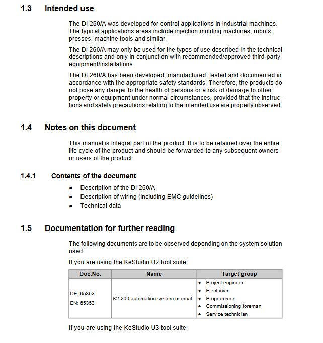
DI 260/A is a digital input module designed by KEBA specifically for industrial automation scenarios. Its core is used to collect external digital signals and transmit them to control systems, adapting to equipment such as injection molding machines, robots, presses, and machine tools. The module is positioned as an engineering level component, only aimed at project engineers, operators, and service technicians (who need to have relevant knowledge of PLC working principles, safety regulations, etc.), and is not directly aimed at end users. Terminal safety instructions need to be integrated into the user manual by the equipment manufacturer.
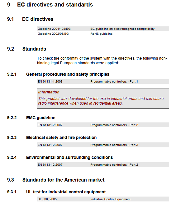
The module complies with standards such as EN 61131-2:2007 and UL 508, and has been certified by EC Electromagnetic Compatibility (2004/108/EG) and RoHS (2002/95/EG) directives. It has high reliability and electromagnetic compatibility and needs to be installed in control cabinets for use. It is prohibited to deploy outdoors or in unprotected environments.
Core Technical Parameters
Power Supply and Consumption
Parameter specifications
Power supply source 24V DC (K-Bus), 5V DC (K-Bus)
Maximum power consumption (24V) 1W
Maximum power consumption (5V) 0.4W
Overvoltage category II
Equipment Class III (EN 61131-2:2007)
Input Performance
Input type, quantity, voltage range, core characteristics
Digital input (Type 1) 16 channel “1” state: 15-30V DC; 0 “state: -3-5V DC shared reference ground, galvanic isolation
Interrupt input 2 channels (DI0/DI1) with the same digital input response time of 100 µ s, 5kHz input filtering
Shake reduction time – non interrupt: 1ms (default)/100ms (configurable); Interruption: Automatic 34 µ s
Cycle time -1ms
Electrical strength -707V (ungrounded connection)
Environmental and Physical Parameters
Category specifications
Working temperature 5 ℃~55 ℃
Storage temperature -40 ℃~70 ℃
Relative humidity 10%~95% (non condensing)
Vibration/impact resistance in accordance with EN 61131-2:2007
Dimensions (height x depth x width) 120mm x 100mm x 32.5mm (including K-Bus plug)
Panel width 22.5mm
Weight 130g
Hardware Structure and Connection
Hardware composition
Front end layout: 16 digital input interfaces (DI0-DI15), with a green LED status indicator on the left side. When the input is in the “1” state, the LED lights up;
Connector: Adopting 5.08mm grid standard terminals, supporting 2-8 pole female connectors (recommended Weidm ü ller model, to be purchased separately), multiple signals can be grouped and used with large terminals (to be adjusted according to the manufacturer’s derating curve);
Address switch: located inside the lower cover on the right side of the module, with 16 bit adjustment, used to set the K-Bus address. The factory default address is 0. Modules of the same type on the same line need to set a unique address, and up to 12 modules of the same type can be cascaded;
Protection design: K-Bus plugs and address switches are both protected by cover plates, and the end module needs to keep the cover plate locked to prevent damage from dust and static electricity.
Wiring specifications
Power wiring: The power supply is taken from K-Bus and does not require an additional external power supply. The 24V DC circuit needs to be equipped with a maximum 10A fuse to avoid module failures causing fires;
Digital input wiring: 16 inputs share a reference ground (front 0V terminal), which must be connected to the 0V terminal to function properly. The input signal is driven by an external 24V power supply and complies with Type 1 input specifications;
Interrupt input wiring: DI0 and DI1 can be configured as interrupt inputs, and the wiring method is the same as that of ordinary digital inputs. Attention should be paid to avoiding false interruptions triggered by interference pulses above 10V;
EMC requirements: Wiring should pay attention to shielding and wiring specifications. For detailed requirements, please refer to the system manual.
Configuration and Operation
Address Configuration
Open the lower cover on the right side of the module to expose the address switch;
Adjust the switch to the target address (0-15) as needed, and the addresses of modules of the same type in the same circuit cannot be repeated;
After the configuration is completed, close the cover plate and lock the end module with the cover plate for protection.
Anti Shake Configuration
Non Interrupt Mode: Set the debounce time to 1ms (default) or 100ms through the configuration tool to suppress interference signals generated by switches, buttons, etc;
Interrupt mode: The debounce function is automatically enabled, fixed at 34 µ s, with invalid configuration parameters to ensure quick response to external signals.
Work Behavior
The module communicates with the control system through K-Bus with a cycle time of 1ms to ensure real-time transmission of digital signals;
The input signal status is visually displayed through green LED, which facilitates on-site debugging and troubleshooting;
Interrupt input has higher priority than regular input and is suitable for scenarios that require quick response, such as emergency stop signals.
Safety and Compliance
Safety requirements
Power safety: Only SELV/PELV rated power supplies (EN 61131-2) can be connected to avoid high voltage risks;
Operation safety: Do not plug or unplug modules with power on, otherwise it may damage the module or cause abnormal control system signals;
Circuit protection: The 24V DC power supply circuit needs to be equipped with suitable fuses, and the maximum nominal breaking current should not exceed 10A.
Compliance and Disposal
Certification compliance: Complies with the EC Electromagnetic Compatibility Directive (2004/108/EG), RoHS Directive (2002/95/EG), meets EN 61131-2:2007, UL 508 industrial control equipment standards;
Environmental disposal: The module belongs to electronic waste and is prohibited from being mixed with household garbage for disposal. It must be disposed of in accordance with local electronic waste recycling regulations, and the materials can be recycled and reused.
Accessories and Documents
Recommended Accessories
Accessory Type Extreme Color Weidm ü ller Order Number
Female connector 2-pole black BLZF 5.08/2 SN SW -170769
Female connector 4-pole black BLZF 5.08/4 SN SW -170771
Female connector 6-pole black BLZF 5.08/6 SN SW -170773
Female connector 8-pole black BLZF 5.08/8 SN SW -170775