Kollmorgen SERVOSTAR 600 (S600) series digital servo drive
Product Overview and Model Code
Product Core Positioning
The S600 series is a digital servo drive launched by Kollmorgen for medium to high power and high-precision motion control scenarios. The hardware version has been iterated to 05.40 and supports multiple types of feedback devices and bus expansion. It can also be equipped with an optional AS restart lock safety function, and is compatible with synchronous servo motors, linear motors, and asynchronous motors. It can expand I/O and communication capabilities through expansion cards. Its core advantages lie in medium to high power coverage, high control accuracy, and flexible expansion. It is widely used in automation production lines, multi axis collaborative equipment, precision machine tools, and other scenarios.
Model coding rules
The model consists of “series+current level+voltage type+function options+expansion card”, and the core coding dimensions and example analysis are as follows:
Explanation of the meaning of the coding section and key codes
Series Identification Core Product Series S601 (1.5ARMS), S603 (3ARMS), S610 (10ARMS), S620 (20ARMS)
Current level Continuous current specifications 01 (1.5ARMS), 03 (3ARMS), 10 (10ARMS), 20 (20ARMS)
Voltage type power supply input type 0 (3 × 208-480VAC)
Function Options Core Function Configuration – NA (No Extension), – AS (Restart Lock Function)
Expansion card optional expansion modules OPT-EI (I/O-14/08), OPT-PB (PROFIBUS), OPT-EC (EtherCAT)
Core Technical Parameters
Power Supply and Current Parameters
Model Supply Voltage Continuous Current (ARMS) Peak Current (ARMS) Maximum DC Bus Voltage (VDC) Heat Loss (W)
S601 3×208-480VAC 1.5 3 675 15
S603 3×208-480VAC 3 6 675 30
S606 3×208-480VAC 6 12 675 60
S610 3×208-480VAC 10 20 675 90
S614 3×208-480VAC 14 28 675 120
S620 3×208-480VAC 20 40(2s) 675 150
Control Performance and Safety Parameters
Dynamic performance: Switching frequency of 8kHz (optional 16kHz below 400V), current loop bandwidth>1.2kHz, speed loop update cycle of 65 μ s/250 μ s, position loop update cycle of 250 μ s
Feedback resolution: Sin Cos encoder supports 1Vpp signal, EnDat2.1/HIPERFACE supports high-resolution absolute feedback
Security function: – AS restart lock function complies with EN954-1, supports security category 1/3, response time ≤ 1ms
Braking circuit: Built in braking resistor (66 Ω for 601/603, 33 Ω for 606-620), supports external braking resistor expansion, braking threshold 400-870VDC
Installation and wiring specifications
Installation Requirements
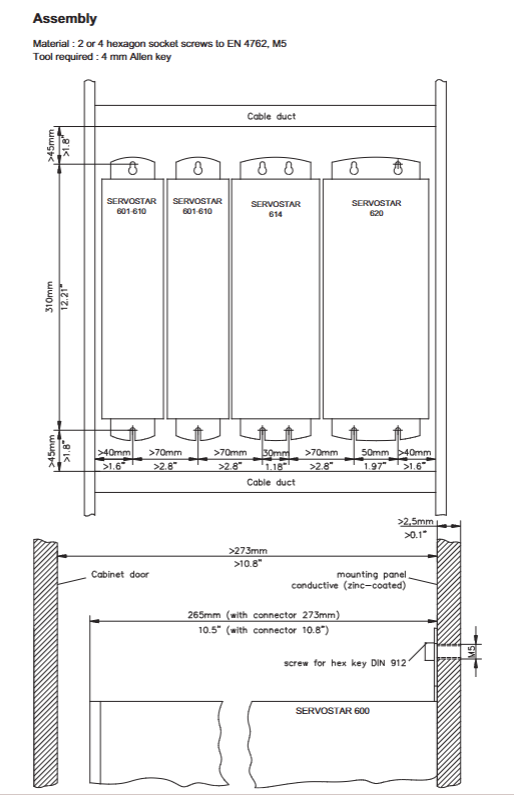
Installation method: Vertically installed on a conductive grounding surface, the control cabinet requires forced ventilation
Cooling gap: top/bottom ≥ 45mm, side ≥ 70mm, high-power models (S614/S620) require the installation of a fan
Mechanical dimensions: Width 70-120mm (70mm for 1.5-10ARMS, 100mm for 14ARMS, 120mm for 20ARMS), height 275mm, depth 265mm, weight 4-7.5kg
Environmental restrictions: Working temperature 0-45 ℃ (with a capacity reduction of 2.5%/℃ for 45-55 ℃), humidity 10-85% (without condensation), altitude<1000m (with a capacity reduction of 1.5%/100m for 1000-2500m)
Core interface wiring
The manual provides detailed wiring definitions for 15 core interfaces, with the following key points:
Power wiring: X0A/X0B interface connected to 3-phase main power supply, L1/L2/L3 phase connected, PE grounding in accordance with IEC 60364 specification
DC bus wiring: The X7 interface supports parallel connection of multiple drivers (total current ≤ 40A), requiring the use of 2.5mm ² shielded cables with a length ≤ 200mm
Motor wiring: X9 interface connects U/V/W three-phase, brake signal BRAKE+/BRAKE – supports 24VDC/2A brake control, motor cable>25m requires motor choke coil 3YL
Feedback wiring: X1 supports Sin Cos/BiSS/EnDet, X2 supports Resolvers, X5 supports SSI/incremental encoders, feedback cables require twisted pair shielding
-AS functional wiring: The X10 interface is connected to a 24V control signal and must be wired according to EN954-1 specifications to ensure activation after mechanical load locking
Parameter Configuration and Control Mode
Basic Configuration
Station address and baud rate: Set through the front panel buttons, CANopen defaults to a baud rate of 500kBaud and supports 10-1000kBaud adjustable
-AS configuration: An external safety relay (compliant with EN954-1) is required, and wiring should be kept away from power cables. Before activation, ensure that the motor is stopped (speed ≤ 5rpm)
Braking threshold: Set through DRIVE. EXE software, default 400VDC (230VAC model), 720VDC (400VAC model), 840VDC (480VAC model)
Core parameter configuration
Parameter Category Key Parameter Function Description Value Range
Current loop Kp proportional gain 0.1-100 V/A
Speed loop Kp Speed loop proportional gain 0.1-100 ARMS/rad/s
Speed loop Ki Speed loop Integral gain 0-1000 Hz
Position loop Kpp Position loop proportional gain 0.1-100 Hz
Electronic Gear GearIn/GearOut Electronic Gear Ratio 1-65535
Current limit I RMS/I Peak Continuous/Peak current limit 0-100% rated value
Feedback configuration FBTYPE feedback type selection 0 (Resolver), 20 (BiSS), etc
Control mode configuration
Torque mode: Supports ± 10V analog commands, with a resolution of 14 bits, suitable for torque closed-loop control scenarios
Speed mode: Supports analog commands, pulse commands, or bus commands, with a stable speed accuracy of ± 0.1% and a maximum speed of 6000rpm
Position mode: Supports step direction (1.5MHz), electronic gear, multi axis master-slave cooperation, and position error window can be set
Electronic gear: supports external encoder as the main shaft, follows proportionally from the shaft, with a gear ratio accuracy of 1/65535
Troubleshooting and Maintenance
Core fault codes and troubleshooting
Fault codes, fault types, common causes, troubleshooting methods
F01 heat sink overheating environment temperature is too high, and the heat dissipation gap is insufficient. Clean the heat dissipation channel, reduce the load, and check the fan
F02 bus overvoltage brake resistor failure, rapid deceleration check brake resistor wiring, extend deceleration time, install external brake resistor
F04 feedback fault feedback cable breakage, wiring error check feedback wiring, measure feedback power supply, replace cable
F06 motor overheating, motor overload, thermal sensor failure to reduce load, check motor thermal sensor wiring, measure winding temperature
F27-AS function failure – AS enables effective adjustment of control logic simultaneously with ENABLE to ensure that the motor has stopped before AS activation
Key points of daily maintenance
Regular inspection: cleaning of heat dissipation channels, fastening of wiring terminals, integrity of feedback cable shielding, recommended every 6 months
Capacitor reformation: When stored for more than 1 year without use, 230VAC single-phase electricity needs to be added for 30 minutes to activate the capacitor
Parameter backup: Backup parameters (. cfg files) through DRIVE. EXE software to avoid configuration loss due to misoperation
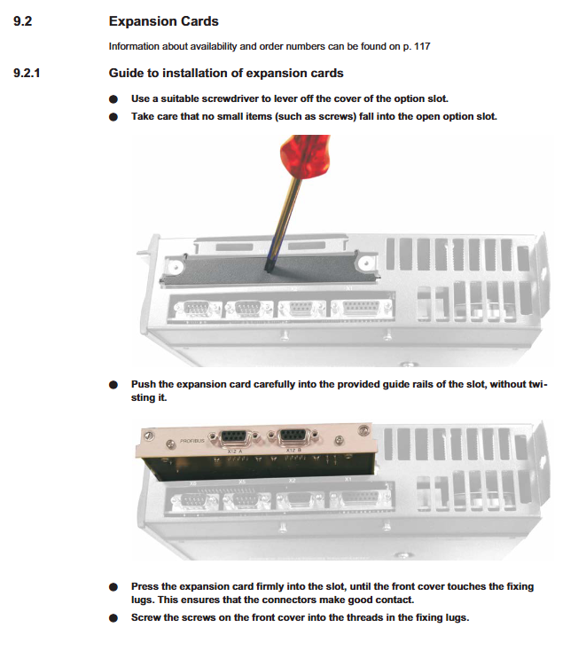
Expansion card maintenance: When inserting or removing expansion cards, power must be turned off. During installation, ensure that the guide rail is inserted into place and the screws are tightened
Expansion Cards and Accessories
Core Expansion Card
Expansion card type, model, core function, interface type
I/O Expansion OPT-EI 14 channel digital input, 8 channel digital output MiniCombicon
PROFIBUS OPT-PB supports PROFIBUS DP protocol SubD 9-pin
EtherCAT OPT-EC supports EtherCAT bus and RJ45 ring network topology
SynqNet OPT-SN supports SynqNet network and multi axis synchronous RJ45
Dual CAN OPT-2CAN separates RS232 and CAN interfaces, supports bus terminal SubD 9-pin x 3
DeviceNet OPT-DN supports the DeviceNet protocol and has adjustable node addresses for MiniCombicon
Special Accessories
Braking resistor: Supports 200-1500W external braking resistor, recommended resistance value of 33 Ω (universal across the entire series)
Cable: Dedicated motor/feedback cable, supports single cable connection, protection level IP67
Connector: X0/X7/X9 dedicated connector, suitable for current carrying requirements of different voltage levels
Software tool: DRIVE. EXE (Windows compatible), supports parameter configuration, oscilloscope monitoring, and fault diagnosis