Honeywell Enhanced Micro TDC 3000 Control System
Product Infrastructure
Core positioning: Enhanced Micro TDC 3000 is a compact industrial control system of the TDC 3000X family, designed specifically for small and medium-sized process industries, supporting centralized and distributed control, balancing control accuracy and deployment flexibility.
hardware architecture
Cabinet design: Dual cabinets (Tower # 1 and Tower # 2), each cabinet is a 4-node multinode module, supporting up to 8 nodes for expansion
Cabinet size: Single cabinet 72cm (height) x 32cm (width) x 58cm (depth), weight 45kg/unit
Core processor: The entire node is equipped with K2LCN processor, which supports hardware level fault diagnosis
Environment and Certification
|Category | Parameter Specifications|
|Working temperature | 0 ℃~45 ℃ (Class C office environment)|
|Storage temperature | -10 ℃~70 ℃|
|Humidity range | 10%~80% (no condensation), temperature change rate<6%/hour|
|Vibration/impact | 5-22Hz 0.254mm displacement; 22-500Hz 0.25g acceleration|
|Certification Standards | CE (89/366/EEC EMC Directive), UL 508, Class I Div 2 Hazardous Areas|
Core Component Details
1. Four core modules
Module type, core configuration, key parameters, functional positioning
Universal Station (US) 6MW memory, dual 150MB Bernoulli cartridge drives support operator/engineer keyboards, optional touch screen/trackball human-machine interaction, system configuration, process monitoring
Application module (AM) 4/8MW memory, supports CL language control strategy execution, custom calculation, data processing core control unit
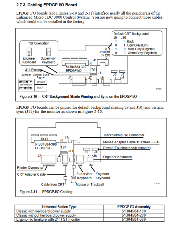
Network interface (NIM) UCN address 1 (primary)/2 (redundant), RS-485 interface connected to APM controller, supporting UCN A/B dual bus process bus communication gateway
History module (HM) 875MB hard drive, 3MW memory storage system software, configuration data, historical trend data storage, and log management
2. Expansion modules and peripherals
extension module
EPLCG (Enhanced PLC Gateway): connects one or more PLCs and supports RS-232 communication
CG (Computer Gateway): connects to the host and supports redundant communication paths
Redundant NIM: Provides backup communication paths to improve reliability
LCN Upgrade Kit: Connect the system to a standard LCN network and support multi cabinet expansion
Peripheral support
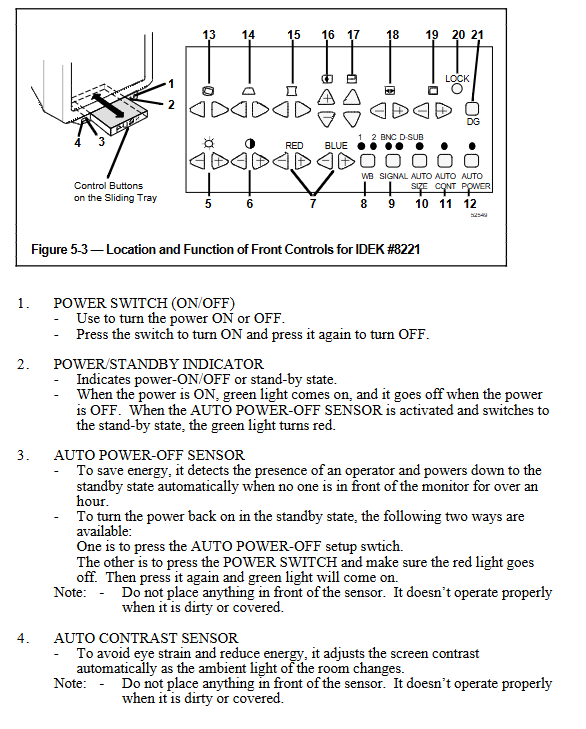
Display: 20 inches (weight 29kg), 21 inches IDEK/HITACHI (weight 33-34kg), supporting VGA/MACII signals
Printer: ASPI-41, supports self checking and diagnostic printing, powered by 120/240VAC
Input devices: Operator membrane keyboard (chemically resistant), Engineer keyboard (hot swappable), Touch screen/trackball
Communication and Integration
1. Bus system
Bus type communication specifications, application scenarios, topology limitations
TPLCN RS-485,5Mbit/s, Token Transfer Protocol Cabinet Node Communication Standard Cable 1.5 meters, optional 10 meter long cable
UCN coaxial cable, connected to APM controller process control signal transmission drop cable with a maximum length of 15 meters, requires terminal resistance
Expansion bus RS-232/485, PROFIBUS, DeviceNet third-party device integration is achieved through gateway modules, supporting multiple master stations
2. Network configuration restrictions
Each C200 controller supports a maximum of 64 I/O units
Each downlink CNI can connect up to 8 uplink devices (CNI/gateway)
RIOM-A gateway supports a maximum of 8 I/O modules
DeviceNet network has a maximum of 64 devices with speeds of 125/250/500KBps
PROFIBUS network has a maximum of 126 slave stations, with speeds ranging from 9.6K to 12Mbps
Power supply and physical specifications
Power supply parameters
|Equipment | Input voltage | Typical power consumption | Maximum current|
|Tower # 1 (including US/AM/NIM) | 120VAC | 266W | 10A (peak)|
|Tower # 2 (including HM) | 120VAC | 185W | 6.5A (peak)|
|20 inch monitor | 120VAC | 79W | 1.14A|
|21 inch monitor | 120VAC | 83W | 1.5A|
|ASPI-41 printer | 120VAC | 210W | 1.75A|
Power supply tolerance: 120VAC ± 15%, 240VAC ± 10%, frequency 47-63Hz
Redundant power supply: supports dual power hot backup and uninterrupted switching
Physical installation requirements
Installation space: minimum 4m x 4m, with 1 meter of maintenance space reserved around the cabinet
Cabinet spacing: Standard cables up to 33 inches (84cm), long cables can be selected up to 10 meters
Grounding requirements: protective grounding (PE) ≥ 10AWG, EMC grounding 4AWG, grounding resistance ≤ 4 Ω
Environmental restrictions: Outdoor installation is prohibited, hazardous areas must comply with Class I Div 2 wiring specifications
Functional characteristics
Control and Data Processing
Control Algorithm: Supports PID regulation, logic control, sequence control, and custom CL language programs
Data acquisition: analog quantity (4-20mA/± 10V), digital quantity (24VDC/120/220V AC), temperature (thermocouple/RTD)
Storage capacity: HM supports 875MB of historical data storage, including event logs, alarm records, and operation records
Custom features: Free Format Logs reports, graphical screen editing, button configuration
Operation and Safety
Permission classification: Operator (basic monitoring), Administrator (parameter modification), Engineer (system configuration)
Password protection: default password “TDC3000 SUPV” (administrator), “TDC3000 ENGR” (engineer), supports custom modification
Display functions: trend analysis, alarm summary, detailed point display, system status monitoring
Safety protection: intrinsic safety wiring isolation, short circuit protection, overvoltage protection, ESD anti-static measures
Maintenance and Diagnosis
Fault indication: LED status light (power OK, error, fan alarm), 7-segment digital tube node address display
Removable Units (ORUs): power module, I/O board, communication module, air filter (51201201-600), printer print head/ribbon
Hot swappable support: Non hazardous areas can plug and unplug modules with power on, and the system automatically recognizes them
Diagnostic tools: HVTS hardware verification testing system, IOTOOL calibration tool, NTOOL network monitoring
Deployment and operation process
Installation process: Site preparation → Cabinet positioning → Cable connection (power/communication/process) → Grounding → Power on testing → System configuration
System startup: HM automatic boot → US loading operating system → configuring network parameters → loading control strategy → startup process monitoring
Daily operation: Call the display screen through the operator keyboard → Monitor process parameters → Handle alarms → Generate reports
Maintenance cycle: Air filter cleaning (30-180 days, depending on the environment), cartridge driver cleaning, printer maintenance