HITACHI EH-150 Programmable Logic Controller (PLC)
System configuration and core parameters
1. System composition
Basic configuration: power module+CPU module+I/O module+basic base
Expansion configuration: Basic configuration+Expansion base+Expansion cable+I/O controller (supports up to 4 expansion bases, depending on CPU model)
System type: standalone system, network system (supporting Ethernet, DeviceNet, PROFIBUS, CPU Link, etc.)
2. Core hardware parameters
Processor: 32-bit RISC processor (Hitachi Super H series), supporting high-speed computing
Storage characteristics: User programs are stored in FLASH memory (not lost in case of power failure), and data memory requires battery backup
Comparison of Core Parameters of CPU Models (Key Models)
|CPU model | Maximum I/O points | Program capacity | Basic instruction processing speed | Number of expansion bases | Special functions|
|EH-CPU104 (A) | 512 | 3.5k steps | 1.0 µ s/instruction | 0 | -|
|EH-CPU308 (A) | 1024 | 7.6k steps | 1.0 µ s/instruction | 1 | Clock, PID, RS-422/485 interface|
|EH-CPU448 (A) | 1024 | 48.5k steps | 0.1 µ s/instruction | 1 | Floating point operation, memory board support|
|EH-CPU516 | 2112 | 15.7k steps | 0.1 µ s/instruction | 2 | 11 slot base support, 2048 point timer|
|EH-CPU548 | 3520 | 48.5k steps | 0.1 µ s/instruction | 4 | 55 slot maximum configuration, multi axis positioning support|
Environmental parameters: working temperature 0-55 ℃, storage temperature -10-75 ℃; Working humidity 20-90% RH (no condensation)
Instruction system
1. Command classification and core information
table
Number of command categories/Description of representative command functions Processing time (EH-CPU448 as an example)
39 basic commands (LD/LDI/AND, etc.) logic operations, timer/counter control 0.1-28.05 µ s/instruction
10 arithmetic commands (addition, subtraction, multiplication, division, etc.) binary/BCD operations, logical operations 19.9-136.5 µ s/instruction
38 types of application commands (shift/transfer, etc.) for data shift, block transfer, encoding and decoding 13-87 µ s/instruction
12 types of control commands (END/JMP, etc.) for program flow control (jump, subroutine) 0.1-194.95 µ s/instruction
High function module transmission of 5 types (TRNS0/RECV0, etc.) universal port data transmission, modem control 57-128 µ s/instruction
71 types of FUN commands (PID/SIN, etc.) for PID operations, trigonometric functions, data conversion 37.2-482.4 µ s/instruction
2. Key Instruction Characteristics
Condition code: Contains 6 types of status identifiers, including DER (data error), ERR (execution error), V (overflow), C (carry), etc., used to determine the execution result of instructions
Applicable I/O types: Supports bit (X/Y/R/L/M, etc.), word (WX/YY/WR, etc.), doubleword (DX/DY/DR, etc.), and constant types
Compatibility: Some commands only support specific CPU models (such as PID commands that support EH-CPU308 (A) and above)
Core module details
1. Module classification and functions
CPU module: 7 models, core functions include program execution, input reception, output control, support for extension base and communication functions
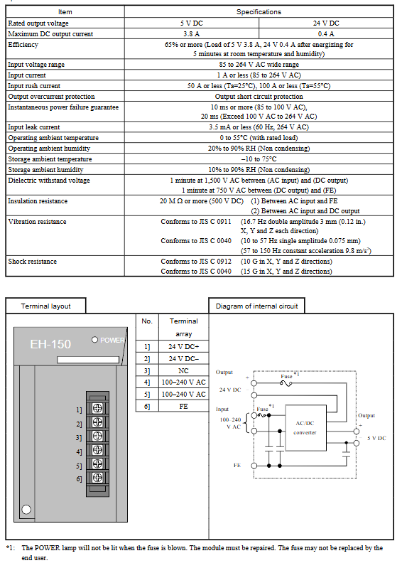
Power module: AC type (EH-PSA, input 100-240V AC), DC type (EH-PSD, input 21.6-26.4V DC), output 5V DC (3.8A)
I/O module:
Input module: 8/16/32/64 points, supports DC (24V)/AC (100-240V) input, some with high cut filters
Output module: 8/16/32/64 points, supporting transistor (sink/source type), relay, bidirectional thyristor output
Communication module: Supports Ethernet(EH-ETH)、DeviceNet(EH-RMD/EH-IOCD)、PROFIBUS(EH-RMP/EH-IOCP) Waiting for the agreement
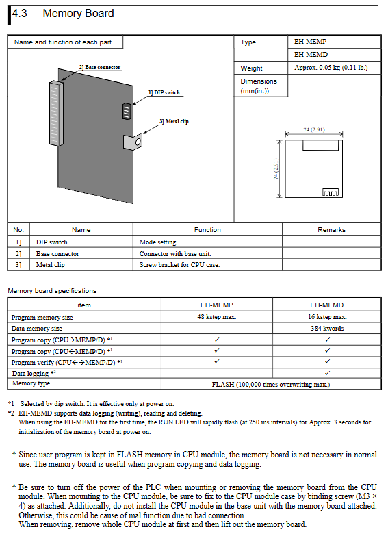
Auxiliary modules: Memory board (EH-MEMP/EH-MEMD, storing programs/data), counter module (EH-CU/EH-CUE), positioning module (EH-POS/EH-POS4)
2. Module installation and wiring
Installation method: DIN rail installation, modules are fixed by locks, and the base supports the installation of 3-11 I/O modules
Wiring requirements: The terminal block should be detachable (M3 screw), the cable should use shielded wire, and the grounding should comply with Class D standards
Practical operation and maintenance
Installation: The base and connection module should be fixed according to the manual requirements to prevent foreign objects from entering the equipment
Programming: Supports online program modification (in RUN state) using LADDER EDITOR software (Windows/DOS version)
Maintenance: Replace the battery every 2 years; Regularly check the module status (LED indicator light); Refer to the error code table for troubleshooting during malfunctions
Fault handling: including error code list (Chapter 12), fault self inspection checklist (Chapter 14), troubleshooting steps, supporting hardware reset and software debugging