HIMA F 8650X Central Module
Core positioning and adaptation scope of the product
Project Details
Product Name: F 8650X Central Module
Adaptation System HIMA PES H51q MS, H51q HS, H51q HRS
Safety level SIL 3 (according to IEC 61508 standard)
Core Application: Industrial Safety Control Scenario, Core Computing and Communication Module
Hardware configuration and performance parameters
1. Processor and Storage
Key specifications of components
Dual INTEL 386EX processor, 32-bit clock synchronization design, ensuring safety redundancy
Clock frequency of 25 MHz, stable support for safety control operations
Operating System Storage Flash EPROM 1 MB Storage System Running Core Programs
User program storage Flash EPROM 1 MB storage custom control program (utilization depends on OS version)
Data storage SRAM 1 MB temporary storage for running data
2. Interface and electrical characteristics
table
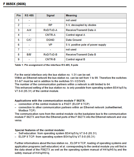
Interface Type Specification Pin Configuration (9-pole)
Serial interface 2 RS 485, with electrical isolation 3-pin (RxD/TxD-A), 8-pin (RxD/TxD-B), 5-pin (DGND)
Watchdog output 24 V DC, maximum 500 mA short-circuit protection design, safe shutdown in case of fault
Working power consumption 5 V DC/2 A stable power supply requirement
Auxiliary power supply 5 V VP (pin 6), 5 V RP (pin 2, diode decoupled) interface power supply support
3. Physical and environmental parameters
Physical structure: Dual European standard PCB, including 1 diagnostic display dedicated PCB
Space requirement: 8 SU (European Standard Installation Unit)
Buffer battery: model CR 2477N (HIMA part number 44 00000 18), lifespan: 1000 days at 25 ℃, 200 days at 60 ℃, recommended for replacement up to 6 years
Key configuration methods
1. Bus station address setting (via switches S1-1-7)
Basic settings: S1-1~5 are used to set addresses 1-31
Extension settings: Combined with S1-6-7, it can be extended to addresses 1-99 (requires OS version ≥ BS41q/51q V7.0-8)
Switch logic: White switch OFF=set, ON=not set
Network restriction: Up to 64 communication partners
2. Transmission rate setting (via switch S1-8)
table
Switch status transmission rate
S1-8 ON 9600 bps
S1-8 OFF 57600 bps
Functional characteristics and operation
1. Diagnosis and troubleshooting
Diagnostic display: 4-digit alphanumeric matrix display, supporting selection to view various types of information
Fault indication: Two LEDs respectively indicate faults in the central module (CPU) and testable I/O module (IO)
Operation buttons: 2 toggle switches for querying detailed fault information; The ACK key is used to reset the fault indication, and when the fault stops, it is equivalent to a system restart
Fault safety: Built in fault safety watchdog ensures safe shutdown triggered in case of malfunction
2. Installation and plugging operations
Disassembly steps: Completely loosen the fixing screws → Press down on the front label to remove the ejection lever → Quickly pull out the module upwards (to avoid triggering the wrong signal)
Installation steps: Place the module on the terminal block → quickly press inward to the bottom (to avoid triggering error signals)
3. Special features (corresponding to OS version)
Self learning function: OS ≥ BS41q/51q V7.0-8 (05.31) support
ELOP II TCP: Supports connection to PADT and Ethernet network communication partners (such as safeEthernet, Modbus TCP), requires cooperation with the F 8627X communication module
Communication path: Central module → Backplane bus → F 8627X → Ethernet network
Maintenance and Precautions
Battery maintenance: When the “BATI” prompt is displayed, it needs to be replaced within 3 months; It is recommended to replace it within a maximum of 6 years when there is no prompt
Configuration check: Before starting, it is necessary to confirm that the bus station address and transmission rate settings of S1 switch are correct
Upgrade note: When upgrading from F 8650 to F 8650X, the fan design needs to be changed synchronously