FANUC Series 0i MODEL F Plus Standard CNC System
Product series and system composition
(1) Core product series
The system is divided into two series according to the type of machine tool, and the core specifications are as follows:
Product Model Applicable Scenarios Control Axis Count (1 Path/2 Paths) Simultaneously Control Axis Count Core Features
0i MF Plus machining center 12 axis/14 axis 4-axis compatible with complex machining centers, supporting multi-path collaboration
0i TF Plus lathe 15 axis/18 axis 4-axis with workpiece loading and unloading control path, suitable for lathe specific requirements
Note: Total number of control axes=number of feed axes+number of main axes (including workpiece loading and unloading control path).
(2) System hardware composition
Control unit: Provides integrated/detachable design, suitable for different cabinet spaces;
Display equipment: covering 10.4 “LCD/MDI units, PANEL+H/+H Pro (10.4″/15 “), FANUC+PC (15″/21.5 “/24”), meeting the operational needs of small to large machine tools;
Operating equipment: handheld operating unit (including emergency stop switch, manual pulse generator), portable manual pulse generator, etc;
I/O unit: divided into MODEL A/B series, supporting multi-point input/output, analog/temperature input, high-speed counter, some models comply with IP67 protection level, and can be configured separately;
Drive system: Equipped with α i-B/β i-B series servo motors, spindle motors, and servo amplifiers, supporting FSSB bus connection.
Core processing functions
(1) Efficient processing technology (reducing cycle time)
Core objective: By optimizing the machining program and dynamically adjusting parameters, the machining cycle time can be shortened. After the application of the example workpiece, the cycle time can be reduced by about 15% (4 minutes and 47 seconds → 4 minutes and 4 seconds);
Key functions:
Intelligent acceleration and deceleration: dynamically adjusting the time constant based on the inertia of the spindle/feed axis, improving the positioning efficiency of large inertial workpieces;
Spindle load control: Real time adaptation of cutting load, optimization of spindle speed and feed rate, and improvement of heavy cutting efficiency;
Sequential processing optimization: Shorten external signal response time and maximize spindle capability;
Efficient processing settings: Compare the current parameters with FANUC default values and configure the optimal parameters with just one click.
(2) Surface fine treatment technology (improving processing quality)
Core objective: To achieve high-quality processing, reduce surface defects, and adapt to precision scenarios such as mold processing;
Key functions:
Smooth tolerance+control: Smooth the path of small line segments within the specified tolerance range, reduce mechanical impact, and ensure that there are no program segment connection marks on the machined surface;
Servo learning control: For repetitive cutting workpieces such as non spherical surfaces and gears, achieve high-speed and high-precision machining with an error of ≤ 2 μ m;
Servo learning type shaking processing: tracks high-frequency shaking commands to finely crush chips without prolonging processing time;
Smooth TCP: When machining with 4-axis linkage, the tool endpoint trajectory is consistent with the instructions, adapting to complex shapes such as impellers and improving CAD/CAM compatibility;
High precision foundation: minimum setting unit of 0.1 μ m, maximum pre reading of 1500 program segments, supporting AI contour control and servo HRV+control.
Usability Design
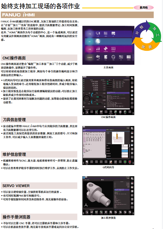
(1) +HMI interactive system
Core advantage: Covering the entire process of “planning processing improvement”, providing integrated operation screens, supporting dedicated keys to return to the HOME screen with one click;
Key functions:
Programming support: G-code wizard (menu based input of complex commands), machining program preview (pre run error detection), command color coded display;
Data management: Centralized management of tool data, with access to tool manufacturer catalog data; Integrate mechanical and CNC/amplifier/motor maintenance parts information;
Auxiliary tools: SERVO VIEWER (displaying operating waveforms, PMC signals), Operator Manual Browser (supporting CNC/machine tool/process manual registration).
(2) User defined functions
Screen customization: Using the FANUC PICURE tool, drag and drop buttons/indicator lights to create a dedicated operation screen that supports multiple languages and full-color display. Network communication and file control can be achieved through scripts;
Program customization: C language executor supports personalized programming, can create pop-up screens, touch screen operation interfaces, and provide CNC/PMC specific functions;
Sequential control customization: FANUC LADDER-III tool supports ladder diagram/Function BLOCK programming, can replace addresses with signal names, supports Ethernet online monitoring and editing, and comes with PMC function library.
(3) Program storage and operation optimization
Storage Expansion: The program memory supports CF cards (up to 2GB, 1000 programs/folders) or PC hard drives (up to 40GB), and supports high-speed GOTO jump;
USB convenient operation: USB programs can be run with one click, and copying and selecting the main program can be completed in one step;
Homework preparation support: Manually control the tool to contact the workpiece for measurement, supporting 8 measurement modes such as end face/outer diameter/inner diameter/width/corner, automatically setting the workpiece coordinate system, and reducing preparation time.
Expansion and connection functions
(1) Robot Easy Connection (CNC-QSSR)
Realize rapid integration of machine tools and robots through four major functions without the need for significant equipment modifications:
Function name, core function, operation advantages
QSSR CONNECT machine connected to robot with 1 Ethernet cable, guided initial setup
QSSR G-CODE CNC Control Robot G Code Instruction Control, Handwheel Positioning Teaching
QSSR AUTO PATH automatically generates motion trajectories with specified starting and ending points, automatically avoids collisions, and simulates confirmation
QSSR ON-SITE is compatible with existing machine tools without the need to modify the ladder diagram/software, with macro variable collaboration
(2) Rich network support
Basic network: Built in embedded Ethernet and Fast Ethernet (100Mbps), supporting program transmission and remote maintenance;
On site network: supports 8 types of industrial networks including FL net, EtherNet/IP (master/slave), PROFINET (master/slave), PROFIBUS-DP, etc., and can connect waterproof I/O devices and sensors (vibration/temperature);
IoT support: Through FANUC MT-LINK * operation management software, centralized collection of equipment information such as machine tools, robots, PLCs, etc., providing standard screens for overall monitoring, operation results, etc., supporting OPC UA/MTConnect protocol.
Security and Maintenance Assurance
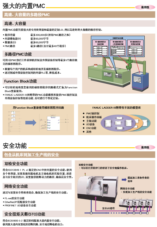
(1) Security function
Double check safety function: compliant with ISO13849-1 PL d standard, dual processors monitor motor position/speed and safety I/O, and double block power path;
Network security function: supports FL net/EtherNet/IP/PROFINET security functions to ensure the safety of production lines;
STO function: The servo amplifier has a built-in safety torque cutoff function, which complies with the IEC61800-5-2 standard and double cuts off the circuit.
(2) High operational efficiency guarantee
Preventive maintenance function:
Insulation degradation detection: The amplifier automatically measures the insulation resistance of the motor, providing early warning of insulation problems caused by cutting fluid;
Fan speed detection: monitoring CNC/servo amplifier fan speed, boxed design for easy replacement;
Power outage protection: Through the power outage backup module (PFB-24/PFB-R/PFB-C), gravity axis anti fall, deceleration shutdown, tool retraction are achieved to avoid equipment and workpiece damage;
Fault diagnosis function:
Fault location: I/O Link+and FSSB support DO short circuit, disconnection, and power transient detection. The detector communication inspection circuit quickly distinguishes detector/cable/amplifier faults;
Diagnostic Screen: Provides fault diagnosis guidance, monitoring, and graphical screens, directly obtaining alarm related system status information on the CNC screen.
Digital twins and supporting tools
(1) Development and simulation tools
Tool Name Core Function Application Value
TOOL PATH OPTIONER: Input machining programs and CAD data, optimize tool paths to reduce surface scratches, improve quality, and adapt to any CAM generated program
CNC GUIDE 2 PC CNC Function Verification and Simulation Reproduction Acceleration/Deceleration/Smoothing Function, Simulating Tool Trajectory and Processing Time, Supporting Custom Interface/Ladder Diagram Debugging
When the SERVO VIEWER idle program is running, it is estimated that the machined surface does not require actual cutting to confirm the machining quality and improve productivity
(2) Debugging and adjustment tools
SERVO GUIDE: integrates the full process operation of servo/spindle adjustment, supports test program programming, parameter setting, data measurement, adjustment wizard automatically optimizes gain and filter, quadrant protrusion compensation automatically adjusts to shorten high-speed and high-precision adjustment time;
MOP simulator: linked with CNC GUIDE 2, providing integrated operation of MDI and operation panel, simulating the actual machine operation feeling, used for personnel training.