FANUC α i series motors and amplifiers maintenance instructions
Product model and core specifications
(1) Summary of Core Product Models
Power module (PS/PSR)
Power regeneration type (PS): 200VAC input (α iPS 5.5~55), 400VAC input (α iPS 11HV~100HV);
Resistive Regenerative Type (PSR): 200VAC input (α iPSR 3, α iPSR 5.5), only supports low-power regeneration.
Servo amplifier (SV)
200VAC input: single axis (α iSV 4~360), dual axis (α iSV 4/4~160/160), three-axis (α iSV 4/4~20/20/40);
400VAC input: single axis (α iSV 10HV~540HV), dual axis (α iSV 10/10HV~80/80HV);
Key parameters: Maximum current of 10A~540A, supporting 1-3 MPG interfaces (some models).
Spindle amplifier (SP)
200VAC input: α iSP 2.2~55, α Ci series (SPMC-2.2i~22i);
400VAC input: α iSP 5.5HV~100HV;
Special models: Supports torque series connection and dual feedback safety function (some models).
motor
Servo motor: α is/α i series (with cooling fan/liquid cooling, compatible with α iSV amplifier);
Spindle motor: α i series (with pulse encoder, supporting rigid tapping, Cs axis control).
(2) Power supply and interface specifications
Power supply voltage: 200VAC ± 15% (control circuit), 400VAC ± 10% (main circuit of high-voltage model), frequency 50/60Hz ± 1Hz;
Communication interfaces: I/O Link bus, FSSB communication (COP10A/COP10B), serial communication (CNC amplifier);
Sensor interface: Supports alpha iM/alpha iMZ/alpha iBZ sensors, analog alpha iCZ sensors, and absolute pulse encoders.
Startup and operation process
(1) Preparation before startup
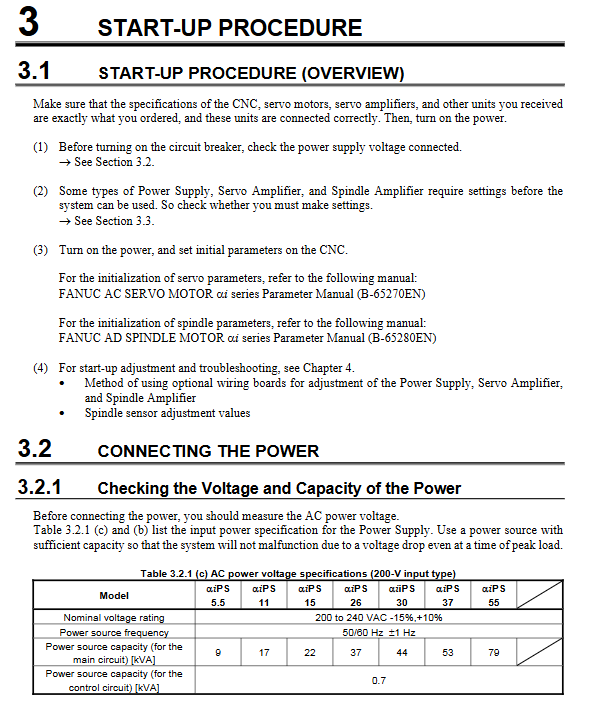
Power check: Measure the input voltage to ensure capacity matching (such as the main circuit capacity of 9kVA for α iPS 5.5);
Wiring confirmation: The protective grounding connection is correct, and the phase sequence of the fan motor power supply is correct;
Component inspection: The amplifier and motor are securely fixed, and the cables are not damaged/loose.
(2) Startup and parameter initialization
Power supply startup: First connect the control power supply, release the emergency stop, and then confirm that the magnetic contactor is engaged;
Parameter settings:
Servo parameters: refer to the FANUC AC SERVO MOTOR α i series parameter manual (B-65270EN);
Spindle parameters: refer to the FANUC AC SPINDLE MOTOR α i series parameter manual (B-65280EN);
Operation confirmation:
Power amplifier: Status LED displays “Ready” (main circuit power supply is normal);
Servo amplifier: VRDY signal is normal, and the motor has no abnormal vibration/noise;
Spindle amplifier: The motor speed is consistent with the command value, and the load current is within the rated range.
(3) Data observation tool
SERVO GUIDE: Supports observing motor speed, current, torque commands, and other data, compatible with Series 30i/16i/18i/21i/0i;
Spindle Inspection Board (A06B-6078-H001): Observe internal data (such as U-phase current, motor speed), check parameter values, and output analog voltage (-5~+5V);
Servo inspection needle board (A06B-6071-K290): detects power input current (IR/IS phase).
Fault diagnosis system
(1) Alarm classification and core code
Power module alarm (α iPS/α iPSR) | Alarm code | Meaning | Key troubleshooting points|
|1 | Input circuit overcurrent | Check power phase sequence and AC reactor specifications|
|2 | Control circuit fan stop | Replace fan motor, clean heat dissipation channel|
|4 | DC Link Undervoltage | Check Input Voltage and Pre Charging Resistance|
|7 | DC link overvoltage | Check the regenerative power and power output impedance|
|E | Input power phase loss | Measure three-phase voltage and check wiring|
Servo amplifier alarm
Common codes: SV0361 (pulse encoder phase error), SV0430 (servo motor overheating), SV0654 (DB relay error);
Troubleshooting logic: First check the status of the STAT3 LED → confirm cable connection → verify parameters → detect sensor signals.
Spindle amplifier alarm
Common codes: SP0001 (motor overheating), SP0002 (excessive speed deviation), SP0027 (position encoder disconnected);
Troubleshooting logic: Distinguish between “startup alarm” (parameter/wiring issues) and “running alarm” (load/heat dissipation issues).
(2) Typical fault handling
Overheating fault (motor/amplifier): Clean the heat sink, check the cooling fan, reduce the load or acceleration/deceleration frequency;
Communication error: Check CXA2A/B interface cable, confirm amplifier ID matching, eliminate electromagnetic interference;
Sensor malfunction: detect feedback signal waveform (such as α iM sensor Vpp=0.5~1.2Vp-p), check cable shielding layer.
Component replacement and preventive maintenance
(1) Replacement process of vulnerable parts
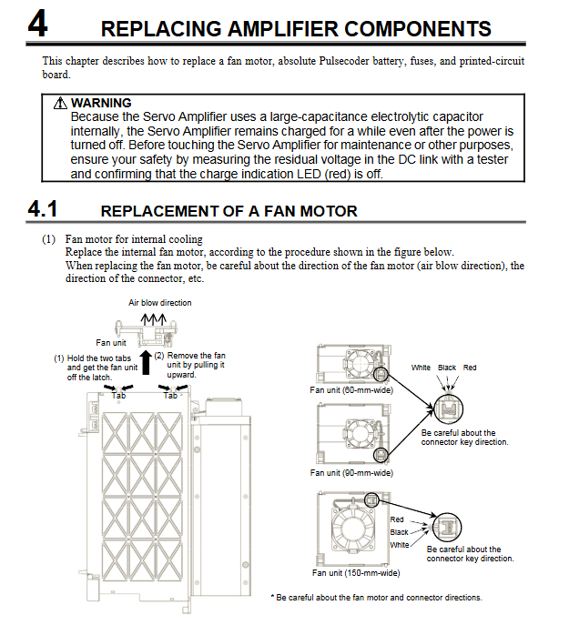
Fan motor replacement
Applicable models: Internal cooling fan (A90L-0001-0510/0511), radiator cooling fan (A90L-0001-0509);
Operation steps: Power off and discharge → Loosen the fixing screw → Remove the connector → Install a new fan (pay attention to the wind direction).
Absolute pulse encoder battery replacement
Attention: It must be replaced with the power on to avoid absolute position data loss;
Replacement object: Independent battery box, servo amplifier built-in battery.
Fuse replacement
Location: Power module (F1/F2), servo/spindle amplifier control board;
Requirement: Use fuses of the same specifications and confirm the cause of the short circuit before replacement.
(2) Preventive maintenance
Regular inspection:
Insulation resistance: measured with a 500VDC insulation resistance meter, it is better to have a resistance of ≥ 100M Ω, and if it is < 1M Ω, the motor needs to be replaced;
Cooling system: Clean the cooling fins monthly to avoid chip/oil mist accumulation;
Cable inspection: Check the shielding layer and connector contact of the cable every quarter.
Storage requirements: When storing the motor, the shaft should be placed horizontally and the terminal box should face upwards; The amplifier should avoid contact with corrosive gases/water droplets.
Periodic maintenance: Refer to the FANUC SERVO AMPLIFIER α i series manual (B-65282EN) for annual maintenance.