Eaton XV400 10.4″/12.1″/15″ MICRO PANEL
Product Model and Configuration
Model classification (divided by core parameters) | Classification dimension | Specific options|
|Screen size | 10.4 “, 12.1”, 15 “|
|Touch screen type | Resistive (4-wire technology), Infrared (logic channel: 10.4 “79 × 59/12.1” 95 × 71/15 “107 × 83)|
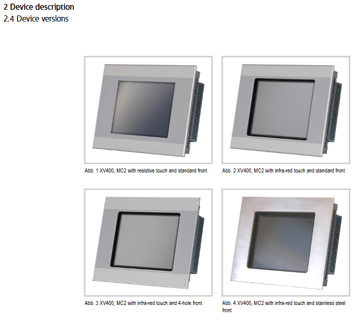
|Front panel style | Standard front panel, 4-hole front panel, stainless steel front panel|
|Typical Model Example | Resistive 10.4 “Standard Front Panel: XV-430-10TVB-1-1x/MC2-430-10TVB-1-1x|
Hardware core parameters | Hardware modules | Specific specifications|
|Processor | 32-bit RISC, 400MHz|
|Memory | DRAM: 64MB; FLASH: Approximately 1.5MB available; NVRAM: Approximately 32KB available|
|External Storage | 2 CompactFlash Card Type I/II slots (for operating system+programs/data respectively)|
|Real time clock | Battery backup (CR2032, 3.0V, 220mAh), backup time after power failure is about 10 years|
|Display Screen | TFT-LCD Color Screen (Resolution: 10.4 “VGA/12.1” SVGA/15 “XGA; Brightness: 350-400cd/m ²)|
Safety regulations and warnings
Definition of safety symbols
DANGER: Emergency danger that may result in death or serious injury (such as explosion risk)
Warning: Potential danger that may result in death or serious injury (such as electric shock risk)
CAUTION (with safety symbol): Potential danger, may cause minor injury (such as electrostatic discharge)
CAUTION (no security symbol): May cause device damage (such as data loss)
Core security requirements
Personnel qualifications: Installation, operation, and maintenance personnel must possess professional qualifications and be familiar with the operating instructions
Prohibited use: The device cannot be used to achieve safety protection functions for personnel or machinery
Environmental restrictions: Operating temperature 0… 50 ° C, storage/transportation temperature -20… 60 ° C, relative humidity 10-95% (no condensation)
Explosion proof requirements: The stainless steel front panel model can be used for Zone 1/2/22 (with pressurized casing), and the grounding resistance should be less than 10 ΩΩ when used for Zone 22
Equipment related risks
Explosion risk: It is prohibited to plug or unplug plugs with electricity in explosive environments and avoid severe impacts
Electric shock risk: There are live parts inside the equipment, and it is prohibited to disassemble it by oneself
Data loss: Powering off/unplugging the CF card during writing may cause data damage, and it is necessary to ensure that there is no writing activity before operation
Installation process and requirements
Installation preparation
Installation position: inside the control cabinet/control board/console, 10.4 “/12.1” can be installed horizontally/vertically, 15 “can only be installed horizontally to avoid direct sunlight
Installation surface requirements: thickness 2-5mm (front panel with 4 holes 2-20mm), flatness ≤ 0.5mm, surface roughness Rz ≤ 120
Cable preparation: Use shielded wire, and the shielding layer needs to be connected to the connector housing with low impedance (compatible with EMC requirements)
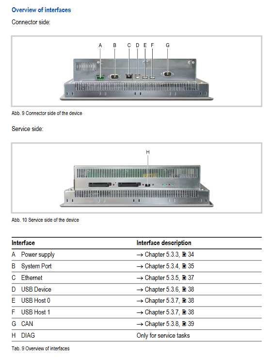
Interface wiring specification
|Interface Type | Key Parameters|
|Power interface | 24VDC SELV, allowable voltage range 20.4-28.8VDC (with ripple 19.2-30.0VDC), maximum power consumption 44W (15 “)|
|Ethernet interface | 10/100Base TX, STP cable is used, the maximum length is 100m, and the firewall is required to isolate the Internet|
|RS232 interface | 9-pin D-Sub male, non isolated, maximum cable length 30m (9600Bit/s)|
|CAN interface | 9-pin D-Sub male, isolated, cable characteristic impedance 120 Ω, maximum length 5000m (10Kbit/s)|
|USB interface | 2 Hosts (USB 2.0), 1 Device (USB 1.1), maximum cable length 5m|
Equipment fixing method
Standard front panel: using 6-12 fixed brackets and threaded pins (maximum tightening torque 0.2Nm), additional brackets are required for IP65 protection
4-hole front panel: fixed with countersunk screws, IP65 protection requires pairing with a middle frame
Stainless steel front panel: Same standard front panel, explosion-proof scenarios require more than 8 fixed brackets
Operation and maintenance
Basic operating procedures
Startup: Insert CF card (slot 0: operating system, slot 1: data) → Secure CF card cover → Power on (no power switch, power on starts) → System configuration+Install applications
Turn off: Confirm that the CF ACT indicator light is off (no writing) → Power off to avoid frequent switching (affecting backlight life)
routine maintenance
Resistive touch screen: Use a soft damp cloth for cleaning (sharp tools/corrosive cleaning agents are prohibited), calibrate in case of abnormal response
Infrared touch screen: Regularly clean the infrared frame (contamination will trigger error prompts), no calibration required
Battery: Integrated non replaceable lithium battery with a lifespan of approximately 10 years
Troubleshooting (Common Problems)
|Fault phenomenon | Possible cause | Solution|
|Device cannot start | Power not connected/CF card without operating system | Check power cable/Insert CF card with operating system into slot 0|
|Touch unresponsive | Resistance screen not calibrated/Infrared frame contaminated | Calibrate resistance screen/Clean infrared frame|
|Display dimming/black screen | Backlight off/backlight failure | Check visualization software settings/send for repair to replace backlight|
|CF card cannot be read | CF card malfunction/incorrect insertion | Replace CF card/reinsert and fix cover plate|
Storage, transportation, and disposal
Storage requirements: Must meet environmental conditions (temperature and humidity, anti condensation), avoid UV exposure (plastic is prone to brittleness)
Transportation requirements: Use original packaging to prevent impact damage, and the transportation process must comply with environmental conditions
Disposal standards:
Prohibited from littering, must be disposed of according to national regulations or returned to the manufacturer
Lithium containing batteries (lithium content 3.4g) and mercury containing cold cathode tubes (mercury<5mg) require professional recycling
Key certifications and standards
Certification/Standard Category Specific Content
Explosion proof certification ATEX 94/9/EC (Zone 1/2/22, according to model)
Safety standards IEC/EN 60950, UL 60950 (document number E208621)
EMC standard 2004/108/EC, IEC/EN 61000-6-2 (immunity), IEC/EN 61000-6-4 (emission)
Product standards EN 50178, IEC/EN 61131-2