EATON Time delay undervoltage module
Basic and Product Positioning
This document is a user guide for Eaton’s delayed undervoltage module (instruction manual number IL5721B33H03), which came into effect in January 2019 and replaced the old version in December 2010. Its core positioning is the remote installation accessories for Magnum DS, Magnum, Power Defense ICCB, NRX, IZM26, IZM9, IZMX and other series of air circuit breakers and molded case circuit breakers. Its function is to provide delayed power supply control for the undervoltage release (UVR) of the circuit breaker, avoid false tripping caused by short-term voltage fluctuations, and support emergency non delayed tripping function. It is suitable for voltage protection scenarios in industrial distribution systems.
Core Functions and Working Principles
Core Functions
Voltage conversion: Receive AC input voltage, rectify it into DC output through a built-in diode bridge, and supply it to the undervoltage release (UVR) of the circuit breaker;
Delay protection: In case of voltage interruption or low voltage, the energy storage capacitor releases energy to provide temporary power supply for UVR for up to 2 seconds, avoiding tripping triggered by instantaneous voltage abnormalities;
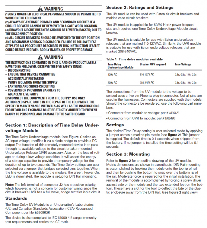
Delay adjustable: Supports 4 delay settings (0.1s/0.5s/1.0s/2.0s), selected by short circuiting the corresponding pins with jumper wires. The default time at the factory is 0.1s (also 0.1s without jumper wires);
Status indicator: After power on, the green “Power On” LED lights up, visually displaying the working status of the module;
Optional function: Can be connected in series with normally closed buttons to achieve non delayed undervoltage tripping when pressed (the button must meet the 3A/250VDC contact rating).
Workflow
Normal power supply: AC power supply → module rectification → DC output to UVR, UVR maintains circuit breaker closed state;
Low voltage/voltage loss: The module detects abnormal voltage, the energy storage capacitor starts, and the UVR power supply is delayed according to the set time;
Delay end: If the voltage is not restored, the UVR loses power and the circuit breaker trips; If the voltage is restored, the module will resume normal power supply;
Emergency trip: Press the optional normally closed button to directly cut off the UVR power supply without delayed tripping.
Key Specification Parameters (Summary Table)
Category specific parameters
Compatible with two versions of UVR voltage: 110-127VAC, 208-240VAC
Power frequency 50/60Hz
Delay gear 4: 0.1s (default), 0.5s, 1.0s, 2.0s
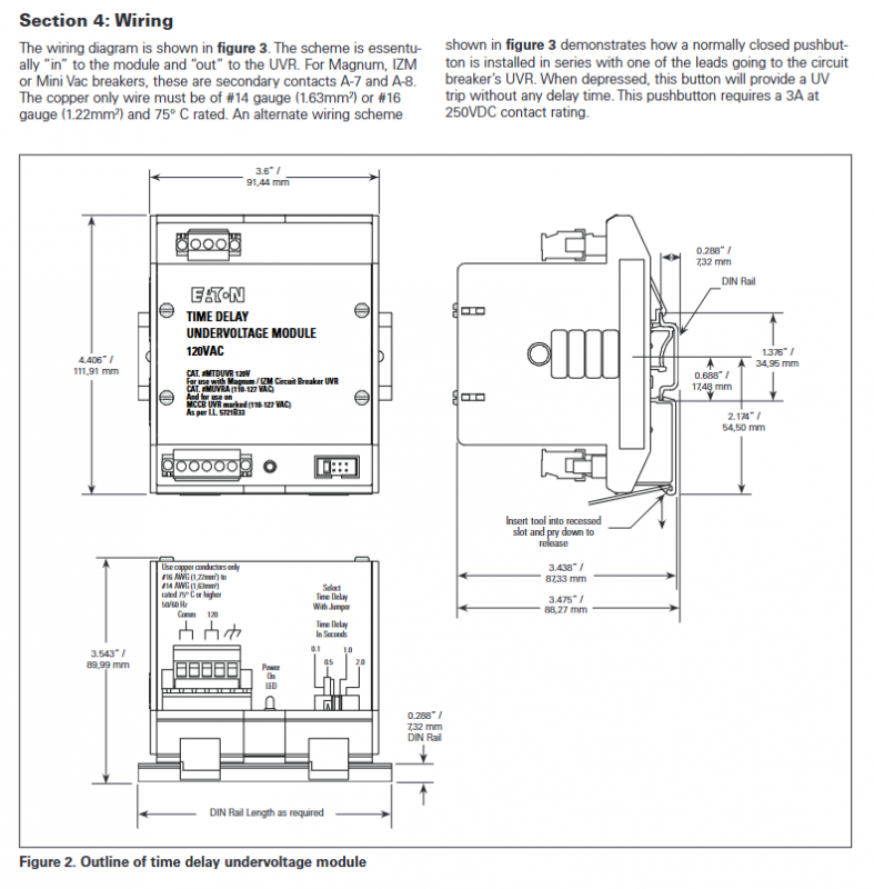
Wiring requirements and specifications: Line 14 (1.63mm ²) or Line 16 (1.22mm ²); Material: Pure copper; Rated temperature: 75 ℃
Connector specification 1. Module → Power supply: 5-pin Phoenix plug (part number 1835122); 2. Module → UVR: 3-pin Phoenix plug (part number 1835106)
Installation method: DIN rail installation (upper hook and lower buckle type)
Certification Standard 1: UL/CSA Approved Components (Document No. E52096SP); 2. Meet the surge immunity requirements of IEC 61000-4-5; 3. CE certification
Adapt to the Magnum/IZM/Mini Vac series of circuit breaker contacts: secondary contacts A-7, A-8
Installation and wiring specifications
Installation process
Installation method: DIN rail installation, steps: ① Hang the top hook of the module on the upper edge of the rail; ② Press the bottom of the module to secure its buckle onto the lower edge of the guide rail (moderate force is required);
Dismantling method: Use a screwdriver to press against the extension foot slots on both sides of the bottom of the module, pry open the plastic buckle to detach from the guide rail, and then remove the module.
Wiring specifications
Basic wiring logic: power supply → delay undervoltage module → circuit breaker undervoltage release (UVR), specifically connecting the secondary contacts of the circuit breaker (such as A-7, A-8);
Optional wiring (no delay tripping): Connect a normally closed button in series on one lead from the module to the UVR, and the button must meet the 3A/250VDC contact rating. When the button is pressed, the UVR power supply is directly cut off to achieve no delay tripping;
Wiring precautions: Only use pure copper wires and ensure that the wire gauge meets the requirements. All wiring must be completed in a power-off state to ensure a secure connection.
Safety operation requirements
Personnel qualifications: Only qualified electricians are authorized to perform module installation, wiring, and maintenance operations;
Power outage prerequisite: Before operation, the power supply of the main circuit and secondary circuit must be cut off. The withdrawable circuit breaker should be moved to the “disconnected position”, and all circuit breakers should be placed in the open state and release the mechanism spring to prevent accidental restart;
Safety rules: strictly follow the five safety rules of “power-off – anti misoperation – electrical inspection – grounding short circuit – isolation of adjacent live parts”;
Spare parts usage: Only Eaton authorized spare parts can be used during maintenance, strictly following maintenance cycles and repair specifications to avoid personal injury or damage to the distribution panel.