KONGSBERG DZ-120 Zener Safety Barrier Unit
Core positioning and functions of the product
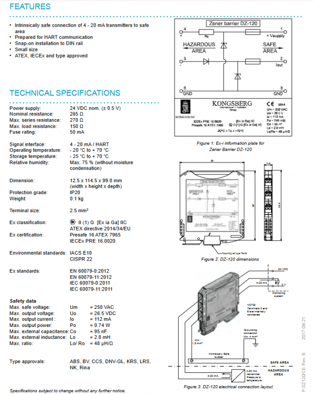
Product type: Single channel parallel diode Zener safety barrier unit, specially designed for Kongsberg brand instruments installed in hazardous areas.
Core function: Provide signal interface and power supply for instrument safety in hazardous areas, capable of connecting 4-20 mA intrinsic safety transmitters, and pre adapted to HART communication protocol.
Core value: As an electrical isolation device between safe and dangerous areas, it prevents safety accidents caused by excessive circuit energy in dangerous areas.
Working principle
Installation prerequisite: It must be installed in a safe area (such as a control room) to protect the 2-wire 4-20 mA/HART signal transmitter in hazardous areas.
Protection mechanism:
When a fault voltage occurs at the safety side terminal, the Zener diode limits the voltage that may occur in the hazardous area, and the resistor limits the current to a safe and acceptable value;
Allow short circuits in connecting cables within hazardous areas without posing any safety risks.
Installation requirements and specifications
The installation of DZ-120 must strictly follow the requirements of intrinsic safety and explosion-proof. The core installation rules and wiring specifications are as follows, which are indispensable:
Installation position and method: Typically installed in the control room processing cabinet, it adopts TS-35 guide rail (in accordance with DIN46277 standard) snap on installation, and requires the use of end plugs to support the equipment.
Definition of wiring terminals:
T4, T5 (blue terminals): Connect intrinsically safe circuits in hazardous areas;
T2, T3: Analog input channels connected to the monitoring system;
T6: The grounding terminal needs to be connected to the intrinsic safety busbar of the system.
Grounding requirements
The equipment needs to be grounded to the system’s intrinsic safety busbar through a minimum of 1.5 mm ² cable;
The intrinsic safety side of the safety barrier must be equipped with a dedicated grounding/grounding plate, and the 3rd and/or 6th terminals of each safety barrier must be connected to the grounding plate through a cable of ≥ 1.5 mm ².
Special conditions for safe installation
① During the final installation in the cabinet, a minimum separation distance of 50 mm should be maintained between intrinsic safety circuits and non intrinsic safety circuits;
② The equipment must be installed in a cabinet with a protection level of at least IP22;
③ The operating temperature range of the equipment is * * -20 ° C ≤ Ta ≤+70 ° C * *;
④ The humidity requirement is a maximum of 75% and there is no condensation.
Safety instructions: For detailed safety operation requirements, please refer to document 373874 K-Gauge Ex I Safety Instructions.
Core product features
Realize intrinsic safety electrical connection of 4-20 mA transmitters from hazardous areas to safe areas, with native support for HART communication;
Adopting DIN rail buckle installation, easy to install without the need for additional fasteners;
Compact in size and lightweight, weighing only 0.1kg, saving cabinet installation space;
Approved by ATEX, IECEx explosion-proof certification, and type certification from multiple classification societies, in compliance with maritime industry standards;
Single channel design, specifically designed for 2-wire transmitters, with strong targeted functionality.
Key technical specifications
The core specifications of DZ-120, including electrical, physical, intrinsic safety and explosion-proof, have clear standards. The core parameters are shown in the table below, and unmarked units are default industry units:
Specification category specific parameters
Power supply nominal 24 VDC (± 0.5 V)
The nominal resistance parameter is 265 Ω; Maximum series resistance 270 Ω; Maximum load resistance 150 Ω
Fuse specification 50 mA
Signal interface 4-20 mA/HART
Temperature range: -20 ° C~+70 ° C; Storage: -25 ° C~+70 ° C
Physical dimensions: 12.5 × 114.5 × 99.0 mm (width × height × depth); Weight: 0.1 kg; Terminal specification: 2.5 mm ²; Equipment protection level: IP20
Relative humidity of environmental parameters: ≤ 75% (no condensation); Compliant with IACS E10 and CISPR 22 environmental standards
The maximum safe voltage of intrinsic safety parameters is Um=250 VAC; Output Uo=26.5 VDC, Io=112 mA, Po=0.74 W; Maximum external capacitance Co=95 nF; Maximum external inductance Lo=2.8 mH; Lo/Ro=48 µH/Ω
Certification standards
Explosion-proof certification
Explosion proof grade: II (1) G [Ex ia Ga] IIC;
ATEX Directive: 2014/34/EU, certification number Presafe 16 ATEX 7965;
IECEx certification: Number IECEx PRE 16.0020;
Explosion proof standards: EN 60079-0:2012, EN 60079-11:2012, IEC 60079-0:2011, IEC 60079-11:2011.
Classification society type certification: ABS, BV, CCS, DNV-GL, KRS, LRS, NK, Rina (covering mainstream maritime classification certifications worldwide).