HONEYWELL IRIS P522 Signal Processor Flame Monitoring Equipment
Core positioning and functions of the product
Product classification and application scenarios
Basic model (P522): 26VDC power supply, suitable for conventional industrial combustion systems (boilers, kilns, etc.);
Upgraded version (P522AC): Supports 85-264VAC wide voltage input, relay capacity increased to 5A, communication baud rate up to 38400, suitable for more complex industrial environments.
Core application: Monitor the combustion flames of fuels such as gas (natural gas, propane), fuel oil (heavy oil/light oil), coal powder, etc., and achieve safety interlock control (automatically cut off the fuel when the flame is lost).
core functionality
Flame detection: By observing the head to collect UV/infrared signals, distinguish between flames and background interference (such as hot refractory);
Self diagnosis: Regularly check and observe the head shutter, electronic components, and cable connections. If there are any abnormalities, it will trigger a lockout;
Safety interlock: In case of flame loss or self diagnosis failure, immediately cut off the fuel supply to the burner to avoid the risk of explosion;
Flexible output: Supports uploading analog signals (0-20mA/4-20mA) to DCS/PLC, with relays directly controlling the burner;
Remote control: parameter configuration and status query are implemented through Modbus protocol, supporting multi device networking.
Key technical specifications
Specification Category P522 Parameters P522AC Parameters
Power input 26VDC ± 5%/-20%, 300mA (single observation head) 85-264VAC (47-440Hz), maximum 0.3A; 22-24VDC backup
Environmental temperature processor: 0-50 ° C; Observation head: 0-60 ° C Processor: 0-52 ° C (CSA)/0-60 ° C (FM); Observation head: 0-60 ° C
Relay capacity maximum 2A (220VDC/250VAC), 60W/125VA maximum 5A (30VDC/125VAC/277VAC)
Analog output 0-20mA/4-20mA, maximum load 360 Ω 0-19.8mA/4-19.8mA, maximum load 360 Ω
Communication parameters RS-4224800/9600 baud rate RS-4224800-38400 baud rate (user selectable)
The cable requires 4-core shielded wire (# 16/# 18 AWG) with a maximum length of 1000 feet, similar to P522. UL ITC/CSA CIC certified cables are required for hazardous areas
Observation head type and adaptation scenario
Observation Head Model Detection Technology Spectral Range Perspective Adaptation Fuel Core Advantages
S506 (UV type) UV photoelectric tube 185-260nm 4 ° natural gas, low NOx gas, strong anti-interference, accurate flame recognition
S506 (self diagnostic model) UV photoelectric tube+shutter 185-260nm 4 ° natural gas support self diagnosis, preventing UV tube from losing control
S509 (dual band) Si+PbS Si: 350-1100nm; PbS: 1100-3000nm 3.9 ° heavy oil, coal powder, mixed fuel multi fuel adaptation, high signal strength
S511 (infrared type) Ge photodiode 750-1900nm 1.6 ° multi fuel structure is simple and stable
S512 (infrared type) PbS photodetector 1100-3000nm 3.2 ° natural gas, heavy oil, coal powder linear response is good, without AGC nonlinear problems
Installation and configuration specifications
Installation Core Requirements
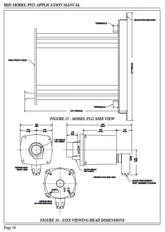
Observation head installation:
Aiming direction: parallel to the centerline of the burner, aim at the root of the flame (UV type needs to aim at the UV radiation concentration area);
Environmental protection: Avoid vibration (with shock-absorbing brackets), temperature ≤ 60 ° C, and fiber optic extension is required in high-temperature environments;
Blow air: Continuously supply clean and dry air (≥ 3CFM, 8-inch water column pressure) to prevent lens contamination;
Pressure limit: The lens can withstand a maximum of 5psi, and an isolation unit is required for overpressure.
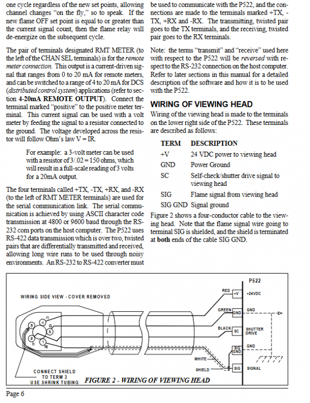
Wiring specifications:
Cable selection: 4-core shielded wire (# 16/# 18 AWG), signal wire shielded separately (braided shielding, aluminum foil shielding is prohibited);
Line separation: The high-voltage ignition line and signal cable are routed separately to avoid electromagnetic interference;
Grounding requirements: Both ends of the shielding layer should be grounded, and the grounding potential of the processor/observation head/power supply should be consistent to avoid grounding loops.
Parameter configuration process
Core parameters:
Flame threshold: FLAME ON (0001-2999), FLAME OFF (0000-2999), must meet an ON/OFF ratio of ≥ 2:1;
Response time (FFRT): 1-3 seconds (compliant with FM standards, maximum not exceeding 4 seconds);
Gain (GAIN): 00-99 levels, adjust signal sensitivity;
Communication parameters: address (0000-0063), baud rate (4800/9600).
Configuration method:
Front panel: Press the FLAME ON/OFF/GAIN buttons to view parameters, use the up and down arrows to modify, and use the STORE button to save;
Remote configuration: Connect to a computer through an RS-232/RS-422 converter or connect to a PLC through Modbus.
Maintenance and troubleshooting
routine maintenance
Regular cleaning: observe the lens (avoid oil/dust obstruction), blow the air pipeline;
Cable inspection: integrity of shielding layer, tightness of joints, and replacement of 150 Ω impedance resistor when the maximum length is 1000 feet;
Parameter calibration: Verify flame signal strength every 6 months, adjust threshold and gain;
Observation head replacement: The lifespan of the UV tube is about 2-3 years, and the lifespan of the infrared detector is about 3-5 years. In case of malfunction, it needs to be replaced as a whole.
Common troubleshooting
|Fault phenomenon | Possible cause | Handling method|
|No flame signal, display 0000 | Observation head not powered, cable disconnected, lens contaminated | Check 26VDC power supply, cable continuity, clean lens|
|Flame exists but relay does not operate | Flame threshold set too high, gain too low | Recalibrate signal, reduce FLAME ON threshold, increase gain|
|Lock up alarm (LOCKOUT light on) | UV tube out of control, self diagnosis failure, signal interference | Reset device, check observation head shutter, eliminate electromagnetic interference|
|Analog output abnormality | Load resistance exceeding standard, wiring error | Ensure load ≤ 360 Ω, check positive and negative pole wiring|
|Large signal fluctuations | Vibration interference, unstable flames | Installing shock-absorbing brackets, optimizing burner operating conditions|