HONEYWELL Sensepoint XCD gas detector
Product Fundamentals and Core Features
Product positioning and application scope
This detector is a gas detection device designed for hazardous areas, suitable for Zone 1/2 in Europe and Class I Division 1/2 in North America. It can detect flammable gases (methane, propane, etc.), toxic gases (hydrogen sulfide, carbon monoxide, etc.), and oxygen (oxygen deficient/enriched). Its core function is to provide gas safety protection for personnel and equipment in industrial sites.
Core Features and Advantages
Multi sensor technology adaptation: Combustible gases use catalytic combustion (CAT) or infrared (NDIR) technology, toxic gases/oxygen use electrochemical (ECC) technology, and infrared sensors have stronger anti poisoning capabilities (lifespan of 5 years);
Safety design: Explosion proof enclosure (Ex d IIC Gb), IP66 protection level, sensors need to be installed downwards (sintered face downwards) to achieve IPX6 waterproofing;
Convenient operation: Supports magnetic and non-invasive operation, calibration, configuration, and status inquiry can be completed without opening the cover, avoiding safety risks in hazardous environments;
Flexible output and communication: Standard 4-20mA signal (source/drain optional), 3 programmable relays (normal on/off optional), optional Modbus RTU communication (maximum transmission of 1000m);
Wide environmental adaptability: working temperature -40 ℃~+75 ℃, humidity 20-90% RH (non condensing), pressure 80-120kPa, suitable for extreme industrial environments.
Key technical specifications
1. Electrical and physical specifications
Specific parameters of specification items
Supply voltage ATEX/IECEx model: 16-32Vdc (nominal 24Vdc); UL/CSA model: 12-32Vdc
Maximum power consumption 5W (at 24Vdc), starting current < 800mA
Signal output 4-20mA (source/drain optional), fault output < 1mA, over range 22mA
Three relays, 5A@250VAC , can be set as alarm 1/alarm 2/fault/suppression
Communication (optional) Modbus RTU (RS485), baud rate 9600/19200, slave ID 1-247
The cable requires a conductor cross-section of 0.5-2.5mm ², and Modbus cables need to be shielded (AWM2464 AWG26-12)
Maximum cable distance 2.5mm ², maximum cable length 1800m (UL 24Vdc)
Material and weight: Aluminum alloy (1.7kg)/316 stainless steel (3.7kg)
2. Testing performance specifications
Gas type detection range accuracy response time (T90) sensor life
Combustible gas (CAT) 0-100% LEL ≤± 1.5% LEL ≤ 25s 3 years
Combustible gas (IR) 0-100% LEL (methane/propane) ≤± 1.5% LEL ≤ 30s 5 years
Oxygen 0-25% Vol ≤± 0.5% Vol ≤ 30s ≥ 2 years
Hydrogen sulfide (H ₂ S) 0-50/100ppm ≤± 3ppm ≤ 50s ≥ 2 years
Carbon monoxide (CO) 0-300/1000ppm ≤± 6ppm ≤ 30s ≥ 2 years
Carbon dioxide (CO ₂) 0-2/5% Vol ≤± 0.04% Vol ≤ 30s 5 years
3. Alarm and calibration specifications
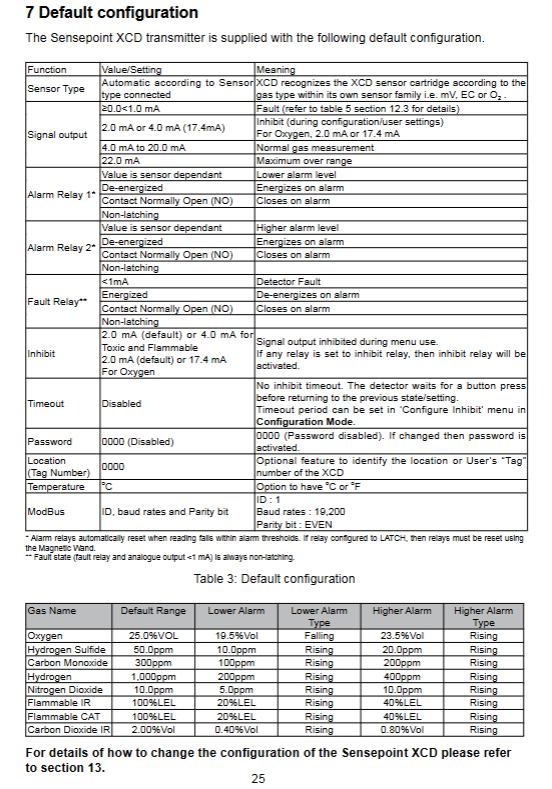
Alarm settings: default low alarm (20% LEL combustible, 10ppm H ₂ S, 19.5% Vol O ₂), high alarm (40% LEL combustible, 20ppm H ₂ S, 23.5% Vol O ₂), supports rising/falling edge alarm;
Calibration requirements: Clean air or nitrogen (20.9% Vol oxygen is required for H ₂ S sensors) is used for zero calibration, and 25-75% FSD standard gas is used for range calibration. The reminder cycle will be automatically reset after calibration;
Calibration process: Magnetic wand enters calibration mode → zero calibration → range calibration → purge gas → complete (the entire process takes about 5-10 minutes).
Installation and wiring specifications
Installation requirements
Installation personnel: Professional personnel who require training and strictly follow local explosion-proof regulations (such as European EN60079-29-2);
Installation location: where gas is prone to accumulate, avoiding rainwater/flood invasion, and reserving maintenance space;
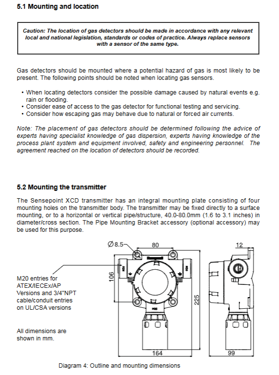
Installation method: Wall mounted or pipeline installation (suitable for 38-95mm pipe diameter), the sensor sintering surface must be facing downwards (ensuring IPX6 protection);
Sealing requirements: Use liquid tight conduit and explosion-proof joint. A sealing joint should be installed within 18 inches near the sensor. Unused cable entrances should be sealed with certified sealing plugs.
Wiring specifications
Cable selection: Industrial grade shielded cable (shielding coverage ≥ 90%), conductor cross-section 0.5-2.5mm ²;
Grounding requirements: The cable shielding layer should be grounded at a single point (one end of the controller or detector should not be grounded at both ends), with internal grounding as the main grounding and external grounding as the auxiliary grounding;
Wiring terminals: Suitable for 0.5-2.5mm ² wires, terminals 1 (24V+), 2 (0V), 3 (4-20mA), Modbus connected to 4 (COM), 5 (TxD), 6 (RxD).
Operation and configuration process
Operation Mode
Monitoring mode: normal working state, displaying gas concentration and status;
Configuration mode: Magnetic wand long press for 3 seconds to enter, password protected (default 0000), configurable detection range, alarm value, calibration interval (30-365 days), suppression current, etc;
Viewing mode: Press and hold the magnetic wand for 1 second to enter, and you can check software version, calibration expiration time, peak concentration, power supply voltage, etc.
Key configuration item
Alarm settings: low/high alarm value, alarm type (rising/falling edge), relay action (power on/off);
Calibration settings: calibration gas concentration, calibration interval, calibration reminder;
System settings: temperature unit (℃/℉), position label (0000-9999), suppression timeout (0-15 minutes).
Maintenance and troubleshooting
routine maintenance
Calibration cycle: It is recommended to be 6 months, and automatic reminders can be set between 30-365 days through the configuration menu;
Sensor maintenance: Avoid contact with corrosive gases/solvents and regularly check if the sensor cover is intact;
Sensor replacement: The same type of sensor must be used, and it must be recalibrated after replacement;
Disposal requirements: Electrochemical sensors (oxygen/toxic) cannot be incinerated and must be environmentally recycled or returned to Honeywell.
Fault and warning codes
|Code type | Code | Description | Processing method|
|Warning | W-01 | Calibration Required | Perform Zero+Range Calibration|
|Warning | W-02 | Overtemperature | Press’ want ‘to clear after the temperature recovers|
|Warning | W-04 | Out of Range (Combustible Catalysis) | After removing the gas, follow the command to clear it|
|Fault | F-01 | Internal I2C fault | Power off and restart, if ineffective, replace the detector|
|Fault | F-02 | Sensor Failure | Replace with a sensor of the same type|
|Fault | F-03 | Excessive zero drift | Recalibrate, if ineffective, replace the sensor|
|Fault | F-06 | Supply voltage too low | Check the supply voltage (≥ 12Vdc/16Vdc)|
Ordering and warranty information
Order Model Rules
The model consists of certification type (ATEX/UL), material (aluminum alloy/316SS), gas type, and communication function (with M as Modbus). Example:
SPXCDALMFX: ATEX certification, aluminum alloy, methane catalysis, M20 interface;
SPXCDUSNHXM: UL certified, 316SS, hydrogen sulfide, 3/4 “NPT interface Modbus。
core components
Essential accessories: Rain cover (SPXCDWP), magnetic wand (SPXCDMAG), calibration cap (S3KCAL);
Optional accessories: Pipe installation bracket (SPXCDMTMB), conduit installation kit (SPXCDDMK), sunshade and shower cover (SPXCDSDP).
warranty policy
Warranty period: 12 months after installation by authorized Honeywell personnel, or 18 months after shipment (whichever comes first);
Disclaimer: Excluding faults caused by disposable batteries, human damage, or sensor poisoning.