
DEIF AGC-3 Automatic Generator Set Controller
The operator manual for the AGC-3 automatic generator set controller of DEIF company in Denmark is aimed at daily operators and provides detailed information on the 15 button functions, 10 LED indicator lights, dual menu system (view menu/settings menu), 5 operating modes (SEMI/AUTO/MAN/TEST/BLOCK), and alarm processing and log query process of the equipment; The device is equipped with a 115 × 220mm backlit LCD display screen (4 lines × 20 characters), which supports viewing generator operating parameters and can record 150 events, 30 historical alarms, and 52 battery test records. It should be noted that installation/operation must be carried out by authorized personnel, and unauthorized disassembly will void the warranty. The factory default setting requires adaptation to the generator set before activation.
Hardware core functions (buttons, LED, display screen)
The button functions (15 core buttons) cover three categories: menu navigation, device control, and alarm viewing. The core functions are shown in the table below:
Function classification key explanation
Menu navigation cursor moves left and right, menu retreats, menu jumps (JUMP) JUMP key allows direct input of menu numbers without the need for step-by-step navigation
The device controls the start and stop of the generator set, the opening and closing of the circuit breaker (effective in SEMI mode), and the start and stop/circuit breaker buttons for parameter adjustment are only available in SEMI/MAN mode
Information viewing: Switch display window, view alarm list, view log list. The alarm list button can directly jump to the alarm page, and the log button can view three types of logs
Mode switching: To switch the operating mode (MODE key), you need to confirm the selected mode through the SEL key
LED indicator lights (10 pieces, green/red dual color) are used to quickly identify device status, with the following core meanings:
Power and equipment status: Auxiliary power on, equipment running normally;
Alarm status: Alarm enabled but suppressed, unconfirmed alarm (flashing), confirmed but not restored alarm (constantly on);
Operation mode: Automatic mode (AUTO) is selected;
Power and circuit breaker status: mains normal (green)/fault (red)/recovery delay (green flashing), mains circuit breaker closed, generator circuit breaker closed;
Generator status: The generator voltage/frequency is normal and the generator is running.
Display screen parameters
Size: 115 × 220mm (4.528 “× 8.661”);
Specification: Backlit LCD text screen, 4 lines x 20 characters, no brightness adjustment function;
Display content: All measured values, calculated values, operating status, and alarm information can be displayed, and specific display items can be configured through PC tools.
Menu and Display System
Menu Structure (Dual Menu System)
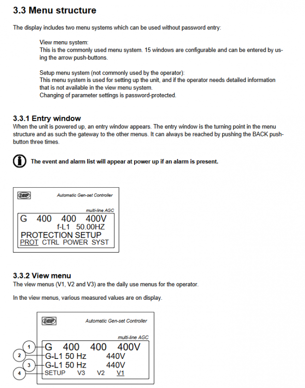
View menu: the core menu for daily operations, no password required, including three submenus V1, V2, and V3, with a total of 15 configurable windows;
Setup menu: a dedicated menu for device configuration, with password protection required for parameter modification, which is rarely used by operators.
Core menu operation
Entrance window: default display upon startup, serving as the “hub” of the menu system. Press the BACK key three times to return at any time; If there is an alarm when starting up, the alarm list will be automatically displayed;
V1 menu: manual switching type, can be switched between 15 windows through buttons, displaying preset measurement parameters;
V2/V3 menu: Automatic switching type, automatically switches with the operating mode of the generator set (start preparation/synchronization/speed up/speed down/normal operation), without manual operation. V2 displays the measured values in full, V3 displays the status text in the first line and the measured values in the last two lines.
Status Text Description
The first line of the display screen can display multiple types of status text, reflecting the device’s operating status. The core categories are as follows:
Operating mode categories: such as Island MAN, AMF AUTO, FIXD POWER ACTION;
Alarm and restriction categories: such as DG BLOCKED FOR START (generator start lock), GB TRIP Externally (generator circuit breaker external trip);
Testing and transition categories: such as IDLE RUN, COOLING DOWN, SYNC HRONISING;
Power management category (G5 option): such as BTB XX DIVIDING SEC (busbar contact circuit breaker partition), BROADCAST Completed (application broadcast completed).
Operating modes (5 core modes)
The device supports 5 operating modes, which can be selected by pressing the MODE key and confirmed by pressing the SEL key. The core functions and applicable scenarios are shown in the table below:
Key Instructions for Key Function Button Permissions in Operation Mode
SEMI (semi-automatic) regulator activation (automatically reaches rated speed after starting), supports manual start stop, circuit breaker opening and closing, automatic synchronization before opening and closing (when allowed), and daily common mode of circuit breaker button activation, balancing manual control and automatic protection
AUTO (automatic) runs automatically according to the preset control type (AMF/fixed power/peak shaving, etc.). Manual button disabled. It is preferred for unmanned scenarios and supports timed start stop and automatic fault switching
MAN (manual) regulator disabled (requires binary input to adjust speed/voltage), supports manual start stop and circuit breaker opening and closing. Before opening and closing, synchronization check must be performed to ensure that the start stop button is effective for debugging or special working conditions. The operator needs to manually control the parameters
TEST: Automatic startup → Perform preset tests (simple/load/full test) → Shutdown → Return to original mode without manual operation permission. Simple test: Startup does not connect to the grid; Load testing: Grid connected with preset load; Full testing: Transfer load to unit, disconnect mains power
BLOCK (lock) prohibits the generator set from starting. It takes effect after selecting the option to shut down during operation. All control buttons are disabled for maintenance or use in case of malfunction. To exit, a password must be entered
Alarm processing and log query
Alarm processing flow
Alarm triggered: automatically jump to the alarm list, only display 1 alarm, the rest need to be viewed by scrolling;
Alarm operation: Scroll through the buttons to switch alarms, select “ACK” and press the SEL button to confirm the alarm; Can directly jump to the first (earliest) or last (latest) alarm;
Alarm display rule: Only active alarms are displayed (alarm conditions still exist), and confirmed and restored alarms are not displayed.
Log query function
Log classification: Includes 3 types of logs, with storage capacity as follows:
Event log: up to 150 records (such as circuit breaker opening and closing, startup, etc.);
Alarm log: up to 30 historical alarms (such as overcurrent, high water temperature, etc.);
Battery test log: up to 52 historical records (such as test success/failure);
Query operation: Press the LOG key to enter the log menu, select the log type by pressing the key, support scrolling up and down, and jump to the first and last logs.
