Danfoss VACON ® NXI FI9-FI14 series frequency converter
Product Overview
Core Structure and Identification
Mechanical structure: divided into power unit (including IGBT inverter bridge, DC link capacitor, charging switch) and control unit (including control board, 5 expansion board slots, fiber/cable interfaces);
Control panel: 9-key operation (Start/Stop/Reset/directional keys, etc.)+3-line display, supports multilingual switching, detachable and remotely operated through cables;
Model code: includes key information such as rated current (e.g. 0003=3A), supply voltage (5=380-500V AC, 6=525-690V AC), protection level (2=IP21, 5=IP54), etc;
Compliance certification: CE, cULus, RCM, KC, etc., classification society certification (LR/BV/DNV, etc.), functional safety compliance with EN 61800-5-2 (STO/SS1 SIL3).
Key Performance Parameters
Category Core Parameters Specification Range
Supply voltage DC input 465-800V (corresponding to 380-500V AC), 640-1100V (corresponding to 525-690V AC)
Output characteristic frequency range 0-320Hz (special application 7200Hz)
Low overload capacity: 110% IL (1min/10min); High overload: 150% IH (1min/10min)
Frequency resolution panel reference 0.01Hz, analog input 0.1% (12 bits)
Environmental adaptability operating temperature -10 ℃ (no frost)~+55 ℃
Storage temperature -40 ℃~+70 ℃
Humidity 0-95% RH, no condensation
Altitude ≤ 1000m (over 1000m, 1% load reduction per 100m)
Delivery, Storage, and Installation
Delivery and Storage
Delivery inspection: ① After unpacking, inspect the appearance for any transportation damage; ② Verify that the packaging label matches the order (model, serial number, rated parameters); ③ Confirm that all accessories are complete (screws, instructions, etc.);
Storage requirements: ① Temperature -40~+70 ℃, humidity 0-95% RH, no condensation; ② Long term storage (>12 months) requires at least 2 hours of electricity per year, or capacitor restructuring as required;
Handling specifications: Select tools according to the weight of the equipment (FI9=65kg, FI10=100kg, FI14=604kg), and it is recommended to use a cantilever crane for FI9 and above.
Installation Requirements
Environmental taboos: no water droplets, corrosive gases, flammable materials, avoid environments with excessive dust/iron powder;
Installation spacing (key for heat dissipation):
|Equipment type | Top spacing (A) | Side by side spacing (B) | Front spacing (C)|
|Full range | ≥ 200mm (7.87inch) | ≥ 20mm (0.79inch) | ≥ 300mm (11.8inch)|
Cooling requirements: ① Single machine should meet the minimum ventilation space, and multi machine installation should avoid hot air backflow; ② The air inlet of the cabinet should be at the bottom, and the air outlet should be at the top. The area of the air inlet/outlet should meet the requirements (such as FI9 requiring an air inlet of ≥ 55000mm ²); ③ Cooling air volume: FI9=750m ³/h, FI14=7200m ³/h;
Installation process: ① Fixed power unit (vertical wall, flat installation surface); ② Install control unit; ③ Check the spacing and ventilation; ④ Connect fiber optic/cable (if not pre installed).
Electrical Installation
Cable and wiring specifications
Cable selection:
|Cable type | required specifications | applicable scenarios|
|Power/motor cable | Heat resistance ≥ 70 ℃, PVC insulation, concentric copper shielding | Main circuit connection (B+/B -, U/V/W)|
|Control cable | Shielded multi-core cable, cross-section 0.5-2.5mm ² | Control signal (analog/digital input/output)|
|Fiber optic cable | Minimum bending radius 50mm, maximum length 8m | Communication between power unit and control unit (FI9-FI14)|
Wiring requirements: ① The motor cable intersects with other cables at an angle of 90 °, and parallel laying should maintain a minimum distance (≥ 0.3m when ≤ 50m, ≥ 1.0m when ≤ 200m); ② The shielding layer needs to be grounded 360 °, with a grounding resistance of ≤ 100 Ω; ③ The terminal tightening torque must comply with the standards (M10:35-45Nm, M12: 65-75Nm);
Grounding specifications: ① PE conductor cross-section ≥ 10mm ² Cu or 16mm ² Al (when S ≤ 16mm ², the cross-section is equal to the phase line); ② Prohibit sharing ground with servo/frequency converter; ③ Type B RCD or RCM equipment needs to be installed (PE conductors may have DC current).
EMC Compliance Requirements
Cable requirements: DeviceNet uses dedicated shielded cables, motor cables use recommended models such as PIRELLI/MCMK, and control cables use low impedance shielded cables;
Installation measures: ① Grommet should be added at both ends of the motor cable, and the shielding layer at the motor end should be grounded 360 °; ② Maintain the default switching frequency of the frequency converter (NXI2: 3.6kHz, NXI2: 1.5kHz); ③ The safety switch must ensure the continuity of EMC protection.
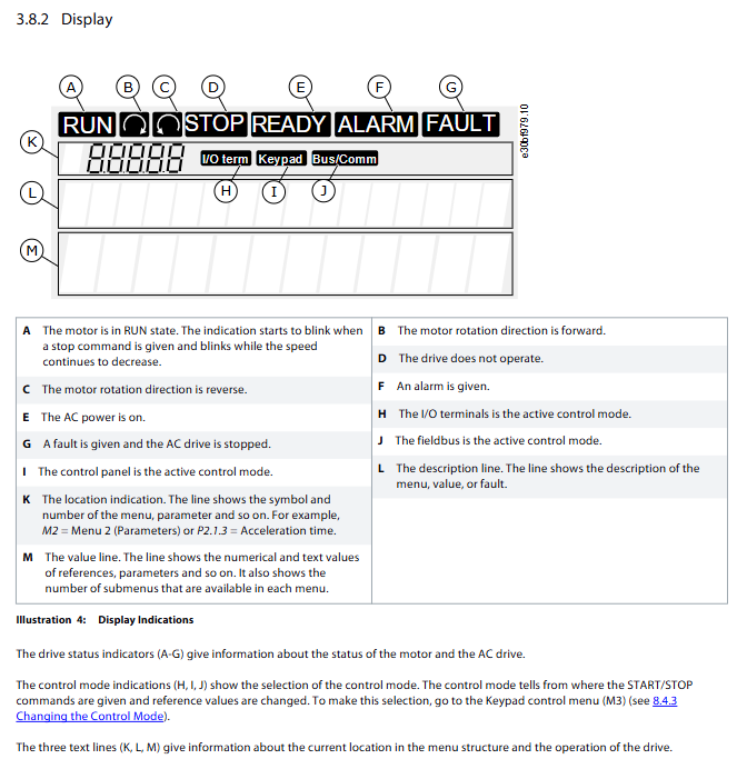
Control panel operation
The control panel contains 7 main menus, with the following core functions:
Core menu functions
Menu Number Menu Name Core Functions Key Operations
M1 monitoring menu monitors 17 real-time data items (output frequency, motor current/speed/torque, DC link voltage, etc.) by pressing up and down keys to switch monitoring items, automatically updated in 0.3s
M2 parameter menu grouping management inverter parameters (such as acceleration time 0-3000s). Some parameters are locked during operation, and editing requires stopping the machine first
M3 keyboard control menu switch control mode (1=I/O terminal, 2=keyboard, 3=fieldbus), set motor direction, frequency reference, long press Start/Stop for 3 seconds to quickly switch to keyboard control
The M4 active fault menu displays the current active faults (up to 10) and fault time records (T1-T16, including frequency/current at the time of the fault). The fault code and brief description can be viewed to guide troubleshooting
The M5 fault history menu stores the last 30 faults, arranged in reverse chronological order. Long press Enter for 3 seconds to clear the fault history
M6 system menu 1. Language/application selection (7 applications);
2. Parameter backup/upload/download/comparison;
3. Password protection (1-65535), parameter locking;
4. Hardware settings (fan control, brake resistor connection, etc.) will reset after switching applications, and need to be backed up in advance
View the status of connected option boards in the M7 expansion board menu, edit board parameters (such as AI/AO signal types), and support expansion boards such as OPTA1/OPTA2/OPTA3
Common Operation Examples
Parameter backup: Go to S6.3->select “Store set 1/2” to save the parameter set, or “Up To Keypad” to upload it to the control panel;
Password setting: Enter S6.5 → Set password (1-65535), automatically activated after timeout, requires password input to modify applications/parameters;
Fault reset: Press the Reset button for 2 seconds, or send a reset signal through the I/O terminal or fieldbus (the startup signal needs to be removed before resetting).
Debugging and Operation
Preparation before Debugging
Safety check: ① Confirm that the power supply has been disconnected and tagged; ② Grounding compliance, terminal fastening; ③ The cooling system is normal and there are no foreign objects blocking it; ④ The connection between the motor and the load is reliable;
Insulation test: ① Motor cable: Disconnect U/V/W from the motor, measure phase to phase and relative to ground insulation resistance>1M Ω (20 ℃); ② DC power cable: Disconnect B+/B -, measure the relative ground insulation resistance>1M Ω (20 ℃); ③ Motor: Disconnect the cable, measure the insulation resistance of the winding to be greater than 1M Ω (20 ℃, test voltage ≥ rated voltage of the motor and ≥ 1000V);
Parameter verification: Confirm that the G2.1 group parameters are consistent with the motor nameplate (rated voltage, frequency, current, speed, cos φ).
Debugging Process
No load test: ① Select keyboard control mode; ② Start the motor and monitor for any abnormal vibration/noise/temperature rise; ③ Test the steering switching and frequency adjustment functions;
Load testing: ① Connect the load and set the maximum frequency reference (adapted to the motor and load); ② Gradually increase the load, monitor the motor current, frequency converter temperature, and DC link voltage; ③ Test the emergency stop function and confirm that the shutdown is normal;
Run checklist: ① The motor is securely installed and the load is not stuck; ② No power compensation capacitor connected to the motor cable; ③ The motor terminal has no mains potential.
Maintenance and Troubleshooting
Maintenance cycle and tasks
Core task notes for maintenance cycle
24 months (storage state) capacitor rearrangement (if not powered on), follow the process in section 10.2, limit the current to 800mA and gradually increase the voltage to the rated DC voltage
6-24 months (operating status) ① Terminal tightening; ② Cleaning of heat sinks/cooling channels; ③ Cooling fan operation inspection; ④ The terminals/busbars are not corroded; ⑤ Shorten the cleaning cycle of cabinet filters in harsh environments
Replacing the cooling fan (main fan, LCL filter fan, IP54 fan, etc.) in 5-7 years will trigger Fault 32 if the fan fails
Replace the DC link capacitor in 8-15 years. The ambient temperature is 30 ℃ and the lifespan exceeds 15 years when the load is 80%
Fault Handling Standards
Fault types: There are 4 types in total, namely Alarm (alarm does not stop), Fault (stop), AR (automatic reset restart), FT (automatic reset failure stop);
Troubleshooting process: ① Check M4 (active faults)/M5 (historical faults) to obtain fault codes; ② Refer to section 12.10 to confirm the cause of the malfunction (load/cable/parameters/hardware, etc.); ③ Take targeted measures (such as overcurrent checking for cable short circuits and overvoltage extending deceleration time); ④ Reset the fault and test it;
Common fault examples:
|Fault code | Fault type | Common causes | Troubleshooting measures|
|Fault 1 | Overcurrent | Motor cable short circuit, sudden load increase, motor model mismatch | Check cable insulation, load status, motor parameters, and perform identification operation|
|Fault 2 | Overvoltage | Short deceleration time, spike in supply voltage, regenerative load | Extended deceleration time, activation of overvoltage controller, installation of braking resistor/chopper|
|Fault 14 | Inverter overheating | Insufficient cooling air volume, dust accumulation on heat sink, high switching frequency | Clean heat sink, check fan, reduce switching frequency (if allowed)|
Core specification supplement
Power level (taking 465-800V DC as an example)
Inverter model, shell size, rated current IL (A), 10% overload power (40 ℃, kW), 50% overload power (40 ℃, kW)
NXI_0168 5 FI9 170 90 75
NXI_0385 5 FI10 385 200 160
NXI_0920 5 FI12 920 500 450
NXI_1450 5 FI13 1450 800 710
NXI_2700 5 FI14 2700 1500 1200
3.8.2 Protection Function
Covering multiple protections such as overcurrent, overvoltage, undervoltage, ground fault, motor phase loss, inverter overheating, motor overheating/stalling/underload, IGBT temperature protection, and brake resistor overheating.