OMRON SYSDRIVE 3G3MV series multifunctional compact frequency converter
Product specifications and installation requirements
2.1 Core Product Specifications
Voltage level, input type, power range, protection level, weight range
200V single/three-phase 0.1-7.5kW panel installation IP20, IP00 0.6-4.8kg after removing cover
400V three-phase 0.2-7.5kW panel installation IP20, after removing the cover IP00 1.0-4.8kg
2.2 Key Installation Requirements
Environmental conditions:
Operating temperature: -10~50 ℃ (panel installation), -10~40 ℃ (enclosed wall mounted installation);
Humidity: ≤ 95% RH, no condensation;
Environmental taboos: No water droplets, corrosive/flammable gases, dust (especially iron powder), oil stains, chemicals, stay away from strong electromagnetic fields;
Installation method:
It must be installed vertically on a flat surface, with the nameplate text facing upwards;
Reserve heat dissipation space to avoid contact with flammable materials;
5.5-7.5kW models can be used as panel mounted models (IP00) after removing the upper and lower covers, with an ambient temperature of ≤ 50 ℃;
Transportation and Handling:
Hold the heat sink during transportation and do not pull or tug on the cables;
Only use the lifting ring to transport the frequency converter, and do not use it to transport the entire equipment.
2.3 Component Operation
Dismantling/installation of cover plate: First, loosen the fixing screws, press or pull the cover plate in the specified direction, and ensure that the buckle is securely fastened during installation;
Cooling fan replacement: The replacement steps for different width models (68mm/108mm/140mm, etc.) may vary slightly. The core is to remove the fan cover, disconnect the connector, replace the fan with a new one (ensuring that the wind direction is facing the heat sink), and rewire and fix it.
Wiring specifications
3.1 Terminal Definition
Main circuit terminals:
|Terminal symbol | Name | Description|
|R/L1, S/L2, T/L3 | Power input terminal | 200V class single/three-phase input (single-phase connected to R/L1 and S/L2), 400V class three-phase input|
|U/T1, V/T2, W/T3 | Motor output terminal | Three phase output drive motor, prohibited from connecting to AC power supply|
|B1, B2 | Braking resistor connection terminal | Connecting external braking resistors or braking resistor units for absorbing regenerative energy|
|+1,+2 | DC reactor connection terminal | Connect DC reactor to suppress harmonics|
|Negative pole of DC power supply | Connect the negative pole during DC power supply|
|Grounding terminal | 200V class ≤ 100 Ω, 400V class ≤ 10 Ω, directly connected to the motor casing ground|
Control circuit terminal (core):
|Terminal symbol | Name | Specification/Function|
|S1-S7 | Multi functional input terminal | Optocoupler input, 8mA at 24V DC, default NPN type, can be switched to PNP type through SW1|
|SC | Sequence input common terminal | Common terminal of multifunctional input terminal|
|MA/MB/MC | Multi functional relay output terminal | Maximum 1A/30V DC or 1A/250V AC, default fault output|
|P1/P2/PC | Multi functional optocoupler output terminal | Open collector output, maximum 50mA/48V DC|
|FR/FC | Frequency reference input/common terminal | 0-10V DC voltage input, input impedance 20k Ω|
|RP | Pulse sequence input terminal | Response frequency 0-33kHz, high level 3.5-13.2V, low level ≤ 0.8V|
|R+/R -, S+/S – | RS-422/485 communication terminal | Used for serial communication connection|
3.2 Wiring Requirements
Cable specifications:
|Circuit type | Cable requirements | Terminal screw torque|
|Main circuit | 600V PVC cable, wire diameter 0.75-8mm ² (depending on model power) | M3.5:0.8-1.0N · m; M4: 1.2-1.5N · m; M5: 2.5-3.0N · m|
|Control circuit | Shielded multi-core wire, wire diameter 0.5-1.25mm ² | M2: 0.22-0.25N · m; M3: 0.5-0.6N · m|
Key specifications:
Single phase connection method: 200V single-phase input requires simultaneous connection of R/L1 and S/L2;
Prohibited items: Do not connect AC power to U/V/W output terminals, and do not lay motor cables and power cables in parallel for long distances;
Shielding treatment: Control cables need to use shielded wires, with the shielding layer grounded to reduce interference;
Terminal fastening: The terminal screws must be tightened to prevent looseness from causing fire or equipment damage.
Parameter configuration (179 core parameters)
The parameters are divided into four functional groups, and the core parameters and functions are as follows:
4.1 Function Group 1 (n001-n049): Basic Control Parameters
Parameter Number Name Core Function Setting Range Default Value
N001 parameter write prohibition/initialization selection can modify parameter range, initialize parameters, clear fault logs 0-11
N002 control mode selection 0=V/f control, 1=open-loop vector control 0-1 0
N019 Acceleration Time 1 Acceleration Time from 0% to 100% Maximum Frequency 0.0-6000s 10.0s
N020 deceleration time 1 deceleration time from 100% to 0% maximum frequency 0.0-6000s 10.0s
The reference current for motor overload detection (OL1) of n036 rated motor current, with OL1 disabled at 0.0 and rated output current ranging from 0.0-150% depending on the model
N037 motor protection function selection 0=universal induction motor, 1=inverter specific motor, 2=no protection 0-2 0
N038 motor protection time: Thermal time constant for motor overload protection, 1-60min, 8min
4.2 Function Group 2 (n050-n079): I/O and Frequency Parameters
Parameter Number Name Core Function Setting Range Default Value
N050-n056 multifunctional input 1-7 selects S1-S7 terminal functions (forward and reverse rotation, fault reset, multi-stage speed, etc.) 1-35 according to the terminal
N057-n059 Multifunctional Output 1-3 Select MA/MB/MC, P1/PC, P2/PC Output Functions (Fault, Running, Consistent Frequency, etc.) 0-19 0, 1, 2
N060-n061 frequency reference gain/bias adjustment analog frequency reference input characteristics 0-255, -100-100, 100, 0
N065 multifunctional analog output type selection 0=analog voltage output, 1=pulse sequence output 0-10
4.3 Function Group 3 (n080-n119): Protection and Compensation Parameters
Parameter Number Name Core Function Setting Range Default Value
N080 carrier frequency selection: Set the carrier frequency according to the default value of the model, 1-4, 7-9 according to the model
N081 instantaneous power outage compensation selection: Processing method during instantaneous power outage (shutdown/continue operation) 0-2, 5-100 0
N082 fault retry times Automatic reset retry times in case of overvoltage/overcurrent fault 0-100
N092 stall prevention during deceleration 0=enabled, 1=disabled (set to 1 when using brake resistor) 0-1 0
The stall prevention level during acceleration/operation of n093-n094 is set at 100% of the rated current of the frequency converter, with a stall prevention current level of 30-200, 170, and 160
N103 torque compensation gain adjustment torque compensation strength 0.0-2.5 1.0
4.4 Function Group 4 (n120-n179): Extended Function Parameters
Parameter Number Name Core Function Setting Range Default Value
N128 PID control selection 0=disabled, 1-8=enable different PID control methods 0-8 0
N130-n132 PID P/I/D parameter setting PID proportional gain, integration time, differentiation time 0.0-25.0、0.0-360.0、0.00-2.50 1.0、1.0、0.00
N139 energy-saving control selection 0=disabled, 1=enabled (only V/f control mode) 0-1 0
N151 RS-422/485 communication timeout detection selects the processing method for communication timeout (shutdown/warning/continue running) 0-4 0
N153 communication slave address setting RS-422/485 communication slave address 00-32 00
N154 communication baud rate 0=2400bps, 1=4800bps, 2=9600bps, 3=19200bps 0-3 2
N176 parameter copying and verification function selection parameter reading, copying, verification, capacity check and other functions rdy Sno rdy
4.5 Parameter Operation Rules
Some parameters cannot be modified during operation and need to be adjusted after shutdown;
Parameter initialization can be set through n001 (default parameters for 2-wire/3-wire systems);
Parameter copying can be done through a digital operator (with n176 and n177 parameters), and only supports copying between frequency converters with the same voltage level and control mode.
Operation and monitoring
5.1 Operation panel functions
Core components:
FREQ adjustment knob: Set frequency reference in local mode (0Hz – maximum frequency);
Mode button: Switch between FREF (frequency reference), FOUT (output frequency), IOUT (output current), MNTR (multifunctional monitoring), F/R (forward/reverse), LO/RE (local/remote), PRGM (parameter) modes;
Add/Remove keys: adjust parameter values, monitor project numbers;
Enter key: Confirm parameter settings and monitor item selection;
Run button: Start the inverter in local mode;
STOP/RESET button: Shutdown in local mode and reset in case of malfunction.
5.2 Monitoring Projects (U-01~U-18)
Monitoring project functional units
U-01 frequency reference Hz
U-02 output frequency Hz
U-03 output current A
U-04 output voltage V
U-05 DC bus voltage V
U-06 input terminal status-
U-07 output terminal status-
U-08 torque monitoring (vector control only)%
U-09 Fault Log (Last 4 Times)-
U-11 output power W
U-13 cumulative operating time (only 5.5-7.5kW) x 10H
U-16~U-18 PID feedback/input/output%
5.3 Operating Mode
Local/Remote Switching: Switching through LO/RE mode or multifunctional input terminals. Local mode is controlled by the operation panel, while remote mode is controlled by external terminals or communication;
Forward and reverse control: By using the F/R mode key, multifunctional input terminal, or communication command control, n006 can disable reverse operation;
Multi speed operation: Set the 8/16 frequency reference through n024-n032, n120-n127, and select it through the multifunctional input terminals (S5-S7, etc.);
Jogging operation: Trigger the jogging frequency (n032 setting) through the multifunctional input terminal, with priority higher than multi-stage speed;
PID control: When enabled, it can achieve closed-loop control and is suitable for scenarios such as pumps and fans. PID feedback input, target value, and P/I/D parameters need to be set.
Maintenance and troubleshooting
6.1 Daily Maintenance
Cooling fan: Replace once every 5-7 years, or promptly replace in case of abnormal noise or malfunction;
Parameter backup: Regularly copy parameters through digital operators to avoid parameter loss;
Cleaning: Regularly clean the dust on the heat sink and fan to maintain smooth ventilation;
Long term storage: If not used for more than 1 year, consult an OMRON sales representative and perform capacitor restructuring if necessary.
6.2 Fault classification and handling
Fatal Errors: After triggering, the frequency converter shuts down and the fault output takes action. The fault needs to be eliminated before resetting. Common faults are as follows: | Fault Code | Fault Name | Probable Cause | Troubleshooting Measures|
|OC | Overcurrent | Output short circuit/grounding, incorrect V/f parameters, excessive motor capacity | Check motor cables, adjust V/f parameters, replace and adapt frequency converter|
|OV | Overvoltage | Excessive regenerative energy, unconnected braking resistor, high power supply voltage | Connect braking resistor, prolong deceleration time, check power supply voltage|
|UV1 | Main circuit undervoltage | Input phase loss, loose terminals, instantaneous power outage | Check input power supply, tighten terminals, enable instantaneous power outage compensation|
|OL1 | Motor overload | Excessive load, incorrect motor current parameters, multi motor drive | Reduce load, correct n036 parameter, configure thermal relay for each motor|
|OL2 | Inverter overload | Overloaded load, short acceleration time, insufficient inverter capacity | Reduce load, extend acceleration time, replace high-capacity inverter|
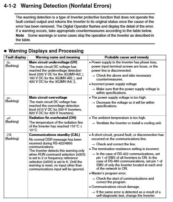
Non fatal Errors: After triggering, the operator flashes and displays, but does not trigger the fault output. After troubleshooting, it automatically recovers. Common warnings are as follows:
|Warning Code | Warning Name | Probable Reason | Troubleshooting Measures|
|Uu (flashing) | Main circuit undervoltage | Input voltage fluctuation, loose terminals | Check power supply voltage, tighten terminals|
|OH (flashing) | Heat sink overheating | High ambient temperature, blocked ventilation, fan failure | Improve ventilation, clean dust, replace fan|
|FAN (flashing) | Cooling fan fault | Fan stuck, wiring fault | Clean foreign objects, check wiring, replace fan|
|OP (flashing) | Parameter setting error | Duplicate multifunctional input parameters, V/f parameter logic error | Correct duplicate parameters, adjust V/f parameters to meet logical conditions|
Fault reset method:
Press the STOP/RESET button on the control panel (make sure there are no running command inputs);
Trigger reset through the multifunctional input terminal (set as fault reset function);
Disconnect the main circuit power and then power it back on.