Saia Burgess PCD4.U100 Upgrade Kit User Guide
Upgrade and Migration Core Process (11 Steps)
The core logic of the upgrade is to replace the PCD4 CPU, connect to the PCD2/3 system, and adapt software/programs. The specific steps are as follows:
Remove the PCD4 CPU and retain the original power supply;
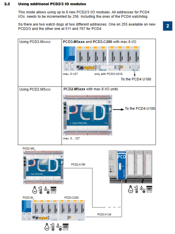
Connect the PCD2/3 system with dedicated cables (PCD2.K106 for PCD2.M5xxx and PCD3.K116/PCD3.K106 for PCD3.Mxxxx);
Select the address mode (starting from 0/256, see 3.3 for details);
Install adapter software: Saia PG5 ® 1.4.300 Patch15+or Saia PG5 ® 2.0.150 SP1+;
In PG5 ® Activate PCD4 FBox and FBs in 2.0;
Backup old project files and upgrade projects from PG3/PG4 (remove old CPU exclusive functions, do not recommend upgrading without original projects);
In PG5 ® Select NT-OS CPU (PCD2.M5_/PCD3.M_) in the hardware/device configurator;
Fupla programming: FBoxes automatically update after opening the project;
IL programming: If FBs are updated, they will automatically adapt. If not, a 2-second system startup delay needs to be added;
Complete user program modifications;
Download the program to the CPU to complete the upgrade.
Address Mode Selection (Core Configuration)
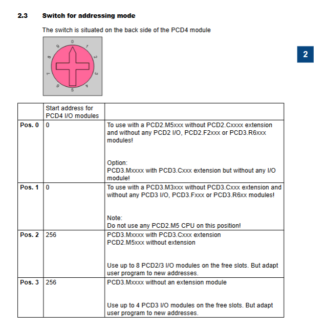
The address mode is controlled by the switch on the back of the PCD4.U100 module, which is divided into two types: 0 start and 256 start, adapted to different hardware expansion requirements. The corresponding rules for the 4th gear of the switch are shown in the table below:
table
Hardware adaptation requirements for switch position PCD4 I/O starting address
0 0 PCD2.M5xxx (no PCD2.Cxxxx extension, no I/O/F/R module); PCD3.Mxxxx (with PCD3.Cxxx extension, without any I/O/F/R modules)
1 0 PCD3.M3xxx (no PCD3.Cxxx extensions, no I/O/F/R modules); Prohibit the use of PCD2.M5 CPU
2 256 PCD3.Mxxxx (with PCD3.Cxxx extension), PCD2.M5xxx (without extension); Up to 8 PCD2/3 I/O modules can be added, and the program needs to adapt to the new address
3 256 PCD3.Mxxxx (without expansion module); Up to 4 PCD3 I/O modules can be added, and the program needs to adapt to the new address
Key rules for two core address modes:
0 Starting address: No new PCD2/3 I/O modules can be added. PCD2.M5xxx is prohibited from using slots 0-7, and PCD3.Mxxxx is prohibited from using slots 0-4; The watchdog address for PCD4 is 255/511, and the watchdog address for the new CPU is 255;
256 starting address: Up to 8 new PCD2/3 I/O modules can be added, and all PCD4 I/O addresses need to be added with 256 (including watchdog). The final PCD4 watchdog address is 511/767, and the new CPU watchdog address is still 255.
Serial Communication Specification
Port replacement: The serial port of the old PCD4 CPU needs to be replaced with the serial port of the new CPU, and only the serial interface of the new CPU is supported;
Starting rule for address:
Only using onboard serial ports, without PCD2/3 E/A modules: PCD4 I/O addresses start from 0;
Using the PCD3. Fxxx/PCD2. Fxxx communication module: The PCD4 I/O address starts from 256, and the user program needs to adapt to the new address range;
PCD3 system limitation: Supports up to 3 onboard serial ports.
Differences in Core Functions between New and Old Systems
Function/Module Old System/Low Version Module New System/PCD4.U100 Kit
PCD4-N210 vs PCD4-N200 N200 only monitors+5V and input voltage, ± 15V fault not detected N210 comprehensively monitors+5V, ± 15V output voltage and input voltage
XOB5 exception handling dependency/IOQUIT signal, used for I/O related exceptions/IOQUIT signal failure, XOB5 is no longer valid, XOB5 needs to be marked as a comment in the program
XOB1 fault detection – detecting power supply faults on the PCD4 I/O bus/PCD3.C200 expansion faults, with a fault detection delay of approximately 500ms
Hardware compatible with PCD4-N2x0. Older versions of PCD4-N2x0 require hardware version B or an update, as older versions may damage PCD4.U100
Compatible and unsupported items (hard specification)
Compatible with hardware/software
Type Compatibility Specification Key Remarks
The main control CPU PCD2.M5xxx/PCD3.Mxxxx needs to be equipped with NT OS firmware, version ≥ 1.10.16
Power module PCD4. N2x0 hardware version B or updated
Programming software Saia PG5 ® 1.4.300 requires installation of Patch 15 or higher version
Programming software Saia PG5 ® 2.0.150 requires installation of SP1 or higher version, and it is prohibited to use the media mapping configuration of the device configurator to configure PCD4 I/O
Unsupported Items
Module: The entire series of PCD4. HXxx modules are not supported;
Port: The serial port of the old PCD4 CPU is not supported, only the new CPU port is valid;
Programming: PG5 ® The media mapping function in 2.0 cannot be used for PCD4 I/O configuration.
User Program Programming Adaptation
Supports Fupla and * * IL (Instruction List) * * programming methods. Due to the improved running speed of the new CPU, IL programming requires targeted adaptation, while Fupla programming is automatic adaptation. The specific rules are as follows:
Fupla Programming
Dependent on PG5 ® Standard FBox library: Analogue Module, HVC Analogue;
Version requirements:
PG5 ® 1.4:Analogue Module≥SP2.6.150、HVC-Analogue≥$2.5.316;
PG5 ® 2.0:Analogue Module≥SP2.6.150、HVC-Analogue≥SP2.6.150;
Activation requirement: PG5 ® 2.0 requires running an activation tool (downloaded from www.sbc-support. com) to enable PCD4 I/O FBox/FBs;
Adaptation logic: After opening the old project, FBoxes automatically updates without the need for manual modification.
IL Programming (Core Adaptation Point)
There are two situations for updating PCD4 FBs and not updating PCD4 FBs, and different PCD4 modules have different adaptation rules:
Updated PCD4 FBs: After opening an old project, FBs automatically update without the need for manual modification;
No update for PCD4 FBs: A 2-second system startup delay must be added (the new CPU is fast to ensure initialization of the PCD4 I/O module). The steps are as follows:
Create the Wait_2s.src file and write the specified IL initialization code;
Place the file at the beginning of the link sequence to achieve a 2-second delay during cold start/startup;
IL adaptation rules for each PCD4 module:
Module model adaptation requirements
Due to the increase in CPU speed, a NOP instruction needs to be added to the read and write instructions for PCD4.W100, and the module base address needs to be added to the operand
PCD4.W300 does not require any code modifications and is directly compatible
PCD4.W400 does not require any code modifications and is directly compatible
PCD4.W500 needs to perform initialization configuration in XOB16, call CFB Control/Config instruction, specify base address and configuration block
PCD4.W600 is consistent with W500, and initialization configuration needs to be performed in XOB16 by calling the dedicated CFB instruction
Multiple W500/W600 module usage:
First, uniformly call the CFB Control command to restart all modules (warm start, parameter 7);
Call the CFB Config command again to configure all modules uniformly;
Core requirement: The total initialization time should be ≤ 3s (equivalent to the old PCD4 module).