SIEMENS SINAMICS S120 Driver
SINAMICS S120 Overview
core components
AC/AC single axis driver: power supply+motor module integration, CU310 DP/PN+PM340, Supports multiple types of motors, suitable for single axis speed/positioning control;
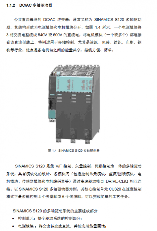
DC/AC multi axis driver: The power supply and motor module are separated and connected through the DRIVE CLiQ high-speed interface. The core is CU320, which also includes power module, motor module, sensor module, etc. It is suitable for multi axis industries (paper/packaging, etc.) and can share energy between axes.
CU320 control capability: maximum speed control of 6 servo axes/4 vector axes/8 V/F axes; The maximum position control is 4 servo axes/2 vector axes. Servo and vector axes cannot be mixed and can be paired with V/F axes.
Power module classification: Basic type (BLM, no feedback), Intelligent type (SLM, feedback+non adjustable bus voltage), Active type (ALM, feedback+adjustable bus voltage).
Indicator lights: CU320, ALM/SLM rectifier module, and motor module are all equipped with LED indicator lights, which reflect equipment operation faults through color/status. If the RDY light of CU320 is always red, it indicates a fault and needs to be cleared before restoration.
Experimental equipment: Based on a 230V input line, it includes CU320 with TB30, 5kW SLM, 3A dual axis motor module, 2 1FK7 synchronous motors, SMC20 encoder module, and Control Box operation box.
SINAMICS S120 Project Configuration
Before configuration, a PC with SCOUT software and DP communication card needs to be prepared to complete the hardware connection. The DP address can be set through binary switch (ON=2 ⁿ, n starts from 0) or P0918 parameter setting (when the switch is fully ON/OFF), supporting both offline and online configuration methods. After configuration, the data needs to be downloaded from RAM to ROM (CF card) for power-off saving.
Offline configuration: Suitable for motors without DRIVE CLiQ interface. The steps are to create a new project → DP communication port setting → drive unit (power/motor/encoder) configuration → project download and storage. When configuring, the control mode (vector/servo) must be selected, and a CU320 cannot be configured with both vector and servo axes simultaneously.
Online configuration: Suitable for Siemens motors with DRIVE CLiQ interface. The steps are: create a new project → DP settings → online connection → restore factory settings → automatic configuration → offline replenishment without DRIVE CLiQ components → download and store. If the firmware version is low, it will be automatically upgraded (3-4 minutes).
Basic debugging
Before debugging, it is necessary to confirm that the project topology is consistent with the actual hardware and supports three basic control methods: control panel, operation box, and BOP20. At the same time, the dynamic characteristics of the motor can be debugged through the Scout tool.
Control panel control: Select axis → Obtain control → Enable axis → Set speed → Start stop, switch axis requires relinquishing control first.
Operation box control: It is necessary to insert the TB30 option board into CU320 and wire it, control the start/stop/reset through digital input (DI), set the speed through analog input (AI), and complete the parameter correspondence between CU320/TB30 and the operation box (such as DI0 corresponding to r0722.0).
Basic operation panel of BOP20: with 6 buttons and background light, it can realize parameter modification, motor start stop, fault reset, support hot plugging, core parameters such as p0003 (access level) and p0008 (transmission object selection), long press the P key for 3 seconds to execute Copy RAM to ROM.
Debugging of motor dynamic characteristics
Trace function: measure time-domain curves such as speed/current, set trigger mode, and analyze overshoot and other issues through curve analysis;
Function generator: Set the forward and reverse rotation of the motor and record the dynamic response curve;
Measuring function: only applicable to servo control, measuring frequency domain Bode plot, optimizing by adjusting proportional gain/integration time, requiring amplitude margin>12dB and phase margin 30-60 °.
Motor optimization
Starting from FW V2.4, motor optimization is supported for Siemens/third-party induction motors and synchronous servo motors, including automatic optimization and manual step-by-step optimization. Before optimization, it is necessary to ensure that the motor is in a cold state, the brake is disconnected, and the mechanical system is safe.
Automatic optimization: Execute Automatic controller setting in Scout to complete motor data calculation and static/dynamic optimization. After optimization, parameters need to be accepted and saved. The overshoot of the motor is significantly reduced after optimization.
Induction motor optimization (vector/SLVC mode)
Step parameter function notes
1. Nameplate parameters (p304/p305, etc.) require input of rated voltage/current/power for motor basic data configuration
2 P340 motor data calculation (fixed/rotor impedance) without enabling frequency converter
3 P1910 Static identification (stator/rotor impedance, leakage inductance, etc.) needs to be enabled, and the motor may rotate 90 °
4 P1960 dynamic identification (encoder testing, speed loop optimization, inertia calculation) is optimized separately under no-load/load conditions, which requires enabling
Optimization of servo motor
The basic steps are the same as induction motors, with the core difference being that dynamic identification requires P1959+P1960 coordination, while static identification may require the motor to rotate 210 °. No load/load optimization requires adjusting the ramp time, current/speed limit according to actual conditions.
Basic positioning
FW V2.4 HF2 and above versions support basic positioning functions, and debugging software needs to be Scout/S120 V4.0+and STEP7 V5.3.3.1+, which need to be activated in offline configuration. It includes 5 core functions and supports control panel/expert parameter table settings.
Activation condition: After configuration, confirm that r108.3=1 and r108.4=1, and the Technology/Basic locator will appear in the project navigation bar.
core functionality
Jogging: divided into speed mode (press button to run, release button to stop) and position mode (automatically stop when running to the target position), require enabling ON/OFF 1 (P840) first;
Zeroing: The incremental encoder needs to be zeroed, while the absolute value encoder only needs to be initialized and calibrated once. There are three methods: setting a reference point (setting the origin at any position), active zeroing (incremental only, three ways), and passive zeroing (dynamic zeroing, which does not affect operation);
Limit: including soft limit (P2582 activated, P2578/2579 set range) and hard limit (P2568 activated, fault stops upon arrival, only reverse operation is allowed), which can limit speed/acceleration;
Program steps: up to 64 steps, supporting automatic continuous/single step execution, with digital input switching between steps;
MDI: Divided into position mode (absolute/relative) and velocity mode, data transmission supports single step (along effective) and continuous (only absolute position, real-time modification).
Parking methods: ON/OFF 1 (normal parking), OFF 2 (free parking), OFF 3 (quick parking, emergency use).
Communication function
S120 supports two communication methods: direct communication with HMI and communication with S7-300 through DP bus, both of which require DP address settings to be completed first. Communication is divided into two forms of data exchange: periodic and non periodic.
S120 communicates directly with HMI: without the need for a PLC, implemented through WinCC flexible. The steps are DP address setting → Step 7, insert HMI Station and configure it → establish a variable table. The variable table DB/DBW follows the rule of DBW=1024 x device number+parameter index number.
S7-300 communicates with S120 DP bus
Message configuration: Common messages such as 370 and 999 (custom), SERVO axis supports 2/3/7 messages, VECTOR axis supports 1/2/20 messages, etc;
Periodic communication: Motor start stop and speed control are achieved through SFC14 (read)/SFC15 (write), with control word Bit0 controlling start stop. The main set value of 4000H corresponds to 100% speed;
Non periodic communication: Drive parameter reading and writing are achieved through SFC58 (write)/SFC59 (read). Based on DPV1 function, up to 240 bytes of data can be exchanged, and the response contains an error code (such as 0x02 indicating parameter value exceeding the limit).
DCC function
DCC (Drive Control Chart) is a graphical CFC programming tool developed by Siemens for SINAMICS/SMOTION. It supports FW V2.5x/SCOUT V4.1x and above, and implements functions such as logic, computation, and closed-loop control.
Core components: DCC editor (CFC programming)+DCC function library (SINAMICS/SMOTION library), divided into DCC-SIMOTION (P/C/D) and DCC-SINAMICS (S120).
Basic functions: logical operations, arithmetic operations, data type conversion, closed-loop control, process functions, system functions.
Configuration compilation process: Add process package → Import library file → Offline programming and allocation of execution group sampling period → Compile and download → Run and debug.
Key points to note
The execution component is fixed/free, and the free execution group sampling period P21000 is 1ms~r21003, which is an integer multiple of the hardware/software sampling time;
DCC will increase the load on CU. The CU for performance 1 requires r9976 average/maximum value to be ≤ 85%. If it exceeds 90%, A50512 alarm will be triggered;
Parameters are divided into direct assignment type (@+number) and BICO type (@ *+number), with BICO type enabling parameter interconnection.
Experimental demonstration: Generate sine and cosine curves through an integrator, associate them with the speed setting parameter P1155, and achieve motor speed variation according to the curve. The maximum speed can be limited by P2900.