SEW EURODRIVE MOVIDYN ® Description of Communication Interface for Servo Controller
SEW EURODRIVE company MOVIDYN ® The Communication Interface Manual for Servo Controllers (January 1997 Edition) focuses on the communication protocols, technical parameters, connection methods, and application scenarios of the RS-232/RS-485 serial interfaces. It specifies that communication adopts a master-slave mode and defines seven types of MOVIDYN ® The message frame type and API/APA specific ASCII protocol are described in detail, including communication direction control, interface monitoring (500ms timeout), and communication configuration with PLC (such as Simatic S5 CP523 module). Multiple application examples of read and write parameters and variables are provided to provide a complete technical guide for data exchange between servo controllers and PC/PLC devices.
Core Communication Protocol
MOVIDYN ® Dedicated protocol (binary frame format)
Communication principle: master-slave mode, where the slave device (servo controller) does not initiate communication actively and only responds to requests from the master device (PC/PLC)
Frame structure composition:
Component Description
Frame identifiers distinguish message types (such as 85H=ENQUIRY, A9H=SELECT)
Servo modules in the unit address identification axis system (0-59, up to 31 MKS, 8 MPx+23 MAS)
Index 16 digit hexadecimal number, corresponding to parameter number (refer to MOVIDYN) ® Parameter List》)
Value parameter data (4 bytes for regular frames, 8 bytes for long frames)
Return code (RC) encoding format indicates the reason for the error (see Appendix for details)
The low byte of the sum of all transmitted bytes in the checksum (CS)
7 types of message frames:
Frame Type Function Frame Identifier (Hexadecimal)
ENQUIRY main device requests to read parameter value 85
DATA responds to the normal parameter value C8 from the device
LONG-DATA responds with an 8-byte long parameter value CA from the device
SELECT main device writes normal parameter value A9
LONG_SELECT main device writes 8-byte long parameter value AD
ACK confirms successful writing from device D2
NACK from device indicating operation failure F3
API/APA proprietary protocol (ASCII frame format)
Applicable scenarios: For APx12 positioning control options (API12 incremental encoder interface, APA12 absolute encoder interface)
Frame structure composition:
Component Description
The frame identifier is fixed as BBH (distinguishing MOVIDYN) ® System and API/APA
Unit address is the same as MOVIDYN ® Protocol (0-59)
Status byte (SB) 8-bit bitmap, controlling data transmission (such as request/data message, whether confirmation is required)
Data length (NL) in hexadecimal format, including the number of bytes for user data and checksum
User data ASCII format commands (such as% RD H00=read variable H00,?)? =Request status)
Checksum (CS) status byte+data length+user data byte sum (ignoring carry)
Definition of Key Status Byte (SB) Bit:
Explanation of Function Values
0 message type 0=data message, 1=request message
3 Confirmation Request 0=No ACK/NACK required, 1=ACK/NACK required
4. Checksum range 0=without axis address, 1=with axis address (firmware V2.0+)
5 checksum range limit 0=0-FF, 1=0-7F (firmware V2.01+)
Interface technology data and connection configuration
RS-232 interface
Technical Specifications:
Parameter specifications
Standard DIN 66020 (V.24)
Baud rate 9600 baud
Data format: 1 start bit+8 data bits+1 stop bit, no checksum
Data direction bidirectional asynchronous, simplex mode
Interface type 9-pin D-type connector (only using 2-5 pins)
Connection requirements:
Cable: 4-core shielded cable, with only one end of the shielding layer grounded
Pin allocation: 2=RxD, 3=TxD, 4=DTR (transmission direction control), 5=GND
Attention: The 2 and 3 pins of the PC and servo controller are cross connected
RS-485 interface
Technical Specifications:
Parameter specifications
Standard RS-485
Baud rate 9600 baud
Data format: 1 start bit+8 data bits+1 stop bit, no checksum
Data direction bidirectional asynchronous, half duplex mode
Interface type terminal block (MPB=X02, MKS=X41, MPR=X02)
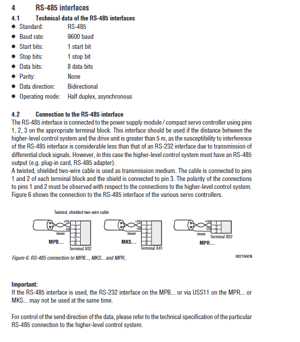
Connection requirements:
Cable: twisted pair shielded two core cable, with shielding layer connected to terminal 3
Pin allocation: 1=RS-485+, 2=RS-485-, 3=Shielding
Applicable scenario: Transmission distance exceeding 5m (anti-interference performance better than RS-232)
Communication Control and Monitoring
Communication direction control (DTR signal)
Core logic: RS-485 is in half duplex mode and requires switching the sending/receiving direction through DTR signals
Timing requirements:
Operation timing requirements
Switch transmission mode at least 2ms in advance and switch DTR signal
After switching the receiving mode and completing the data transmission, delay at least 1ms to switch the DTR signal
After resending and receiving the response, initiate a new transmission at least 2ms apart
DTR processing methods for different servo controllers:
Servo controller type DTR processing remarks
MPB switchable-
MPR/MKS (FIS31:8215952.10) switchable-
MPR/MKS (FIS31:8215952.11/2.12) is fixed at 1 level (+10V)-
MPR/MKS (with USS11) does not require DTR, USS11 automatically reverses data direction
Interface monitoring function
Data transmission timeout monitoring:
Trigger condition: If the complete message transmission is not completed within 500ms after the start of data transmission
Processing logic: Delete received data and wait for new valid frame headers
Remote mode timeout monitoring:
Activation method: Switch to remote mode through the “%+R” command
Trigger condition: No communication interaction within 500ms
Processing logic: Determine communication interruption and stop driving
Release method: Use the “% – R” command to turn off remote mode, or continuously send a “?” status request to reset the timeout counter
PLC communication configuration (taking Simatic S5 CP523 as an example)
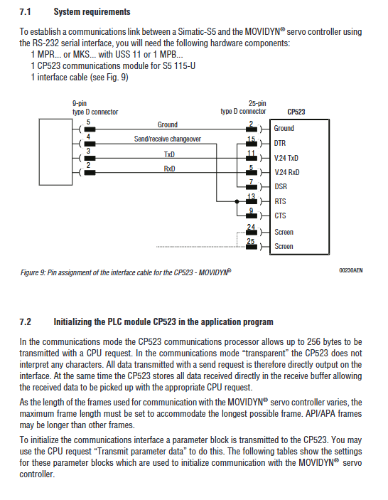
system requirements
Hardware components:
Servo controller: MPR/MKS (with USS11) or MPB
PLC communication module: CP523 (S5 115-U)
Interface cable: 9-pin D-type (PC end) -25 pin D-type (CP523 end)
Communication mode: Transparent mode (CP523 does not parse characters, directly transmits protocol)
Initialize configuration (parameter block settings)
Parameter block 0 (basic configuration):
Byte meaning configuration value (hexadecimal)
0 Request Number (Transmission Parameter Data) 90
2 baud rate (9600 baud) 08
3 Verification (No Verification) 04
6 Data Format (10 bits: 1 start+8 data+1 stop) 05
7 Hardware handshake (enabled) 01
Parameter Block 7 (Communication Mode Configuration):
Byte meaning configuration value (hexadecimal)
0 Request Number (Transmission Parameter Data) 90
Parameter Block Number (Transparent Mode) 71
2-3 character delay time (10ms) 0001
4-5 maximum frame length (256 bytes) 0100
Typical application examples
Example 1: Reading the temperature of the heat sink (axis address 0)
Step operation content
1. Send ENQUIRY frame (5 bytes): frame identifier 85H, address 00H, index 0003H, checksum B8H
2. Receive DATA frames: frame identifier C8H, index 0003H, temperature value (e.g. 2500H=25.0 ℃), checksum F0H
3. Checksum verification: Compare the received checksum with the locally calculated value, and if they match, read them as valid
Example 2: Writing T11 ramp rise time (3.7s, axis address 0)
Step operation content
1. Send SELECT frame (9 bytes): Frame identifier A9H, address 00H, index 001FH, value 0370H, checksum 3BH
2. Receive ACK frames: frame identifier D2H, checksum D2H
3. Checksum verification: Confirm that the ACK frame checksum is valid and the write is successful
6、 API/APA Application Example (Read Status)
Operation purpose: Read API/APA status (including actual position, target position, limit switch status, etc.)
Send request: Frame identifier BBH, address 01H, status byte 11H (request message+including address verification), data length 02H, user data “?”, checksum 53H
Response format: ASCII string, containing fields such as G (actual position), H (target position), O (hysteresis error), P (limit switch status), etc
Special note: If API/APA is not in automatic mode, the program number and line number will be displayed as “–“; When there is an error, the response contains an error sequence (starting with Z, including error identifier, number, and type)