SEW EURODRIVE DFP21B PROFIBUS DP-V1 Fieldbus Interface Description
Hardware installation and wiring specifications
Installation requirements
Key considerations for installation permissions of adaptive devices
MOVIDRIVE ® MDX61B size 1-6: user operable; Size 0: Only SEW engineers need to disconnect the power supply+24V power supply before installation, anti-static (discharge belt/conductive shoes)
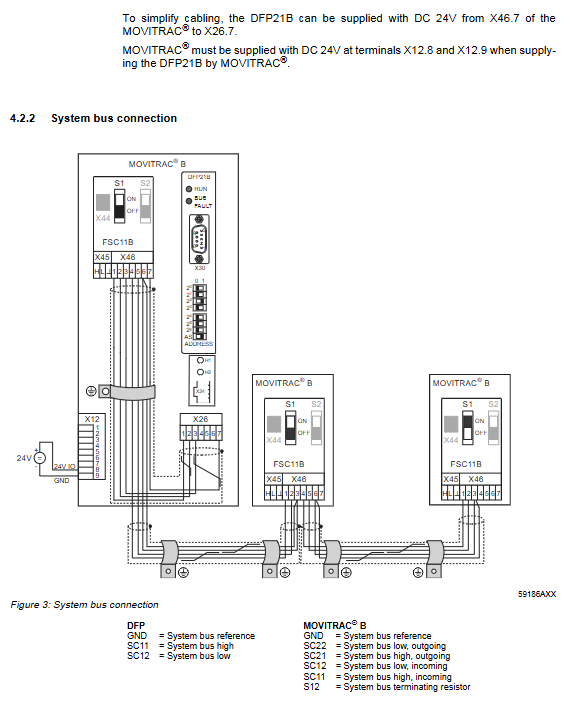
MOVITRAC ® Only SEW engineers need to connect to SBus (SC11=SBus+, SC12=SBus -), and the DFP21B address is fixed at 0
The UOH11B gateway housing can be operated by users and requires an external DC24V power supply (X26.7 terminal), supporting system bus connection
Wiring and shielding
Bus wiring: using twisted pair shielded cable (core wire cross-section 0.75mm ², impedance 120 Ω at 1MHz), 9-pin Sub D plug pins defined as follows:
Pin Function Remarks
3 RxD/TxD-P signal positive terminal
8 RxD/TxD-N signal negative terminal
4 CNTR-P repeater/fiber optic adapter control signal
5 DGND (M5V) reference ground
Shielding requirements:
Only use connectors with metal shells or metal plated shells, tighten the installation screws
The shielding layer has a large area of grounding at both ends to avoid grounding loops
Signal cables and power cables are routed in separate slots to avoid parallel laying
Bus terminal: DFP21B does not have built-in terminal resistors, and requires the use of PROFIBUS plugs with switchable terminal resistors at the beginning and end of the bus (SBus bus terminal resistors are controlled through S1 switch)
Key hardware settings
Site setting: Set through DIP switches (2 ⁰ -2 ⁶) on DFP21B, address range 1-125, default address 4; After modification, the device needs to be restarted to take effect, which can be verified through parameter P093 (Fieldbus address)
Baud rate: Automatic detection of 9.6k-12MBaud, dedicated 12MBaud PROFIBUS connector is required when baud rate>1.5MBaud
AutoSetup function (gateway mode): activated through DIP switch, automatically searches for SBus slaves (up to 8), each slave is assigned 3 process data words, and the search results are indicated by H1 LED (flashing=searching, constantly on=no slave found)
Project Planning and Initiation Process
GSD file configuration
Adaptation scenario GSD file name protocol version DP identification number
MOVIDRIVE ® MDX61B (DP mode) SEW-6003. GSD GSD revision 1 6003hex (24579dec)
MOVIDRIVE ® MDX61B (DP-V1 mode) SEWA6003. GSD GSD revision 3 6003hex (24579dec)
MOVITRAC ® B/Gateway (DP-V1 mode) SEW_6009. GSD revision 5 6009hex (24585dec)
Configuration requirement: The GSD file cannot be modified and needs to be copied to the designated directory of the project planning software (such as the HWConfig directory of Siemens STEP7)
Core configuration steps (using MOVIDRIVE) ® Taking MDX61B as an example)
Step operation content Key parameters
1. Install the GSD file and select the corresponding protocol version of the GSD file
2. Add slave device name: MOVIDRIVE ®+ DFP21
3. The allocation site is consistent with the DFP21B DIP switch settings (1-125)
4. Process data configuration options include “1PD~10PD” and “Param+1PD~Param+10PD”
5. Input/output addresses must be consistent with the PLC program
6. Enable external diagnostics (optional) and configure 9-byte application parameters (00,00,00,06,81,00,00,01,00=enable diagnostic alarms)
Download the configuration to the DP master station and start bus communication. If the BUS FAULT LED goes off, it means the configuration is successful
Variable frequency drive parameter settings
MOVIDRIVE ® MDX61B: Required P100(Setpoint source)=FIELDBUS,P101(Control signal source)=FIELDBUS,P876(PO data enable)=YES
MOVITRAC ® B: Need to set up P100=SBus1/Fieldbus,P101=SBus1,P881(SBus address)=1-8,P883(SBus timeout)=50-200ms
Data Interaction and Parameter Services
Data exchange type
Circular data exchange (process data channel):
Adaptation device process data configuration range access method
MOVIDRIVE ® MDX61B 1-10 I/O word 1-2PD uses Load/Transfer command, ≥ 3PD uses SFC14/15
MOVITRAC ® B/Gateway 3-24 I/O words (3 words per slave) require SFC14/15 (6-48 bytes)
Non cyclic data exchange (DP-V1 service):
C1 main station: supports READ/WRITE dataset 47, with a maximum data length of 240 bytes
C2 main station: Supports InitiatITE/ABORT/READ/RITE services, with up to 2 parallel connections (such as visualization devices+laptops)
Parameter service mechanism
MOVILINK ® Parameter channel (8-byte structure):
Key Explanation of Byte Position Function
The 0 management byte contains the service identifier (0001=READ, 0010=WRITE), data length (11=4 bytes), and handshake bit
The sub index is fixed at 0x00
2-3 parameter index corresponds to the variable frequency drive parameter number (e.g. 8300=firmware version)
4-7 data bytes for storing read/write data or error return codes
PROFIdrive parameter service:
Only supports 2 types of services: Request Parameter (0x01, read parameter), Change Parameter (0x02, write parameter, permanently effective)
Dataset structure: Fixed at dataset 47, supports 1-19 double word parameters, maximum response length of 240 bytes
Error return code structure:
Example of Element Meaning (Illegal Parameter Index)
Error type classification 0x08 (other errors)
Error code error specific reason 0x00 (other error codes)
Additional code SEW exclusive error identifier 0x10 (illegal parameter index)
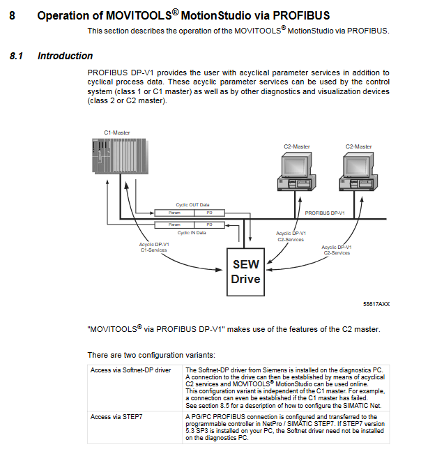
MOVITOOLS ® MotionStudio online operation
Hardware requirements: Siemens CP5512 (PCMCIA)/CP5611 (PCI) card
Software requirements: STEP7 V5.3 SP3+, Softnet DP V6.0+, MOVITOOLS ® MotionStudio V5.20+
Operation process:
Configure PG-PC interface (select CP5512/CP5611, match bus baud rate/station address)
Start SEW communication server and add PROFIBUS communication channel
Press F5 to perform unit scan and display accessible devices
Select the device and switch to online mode for parameter reading/writing/diagnosis
Fault diagnosis and technical data
LED status diagnosis
Solution measures for LED name status reasons
RUN (green) extinguishes the bus, electronic hardware failure restarts the device, multiple failures need to contact SEW service
RUN (green) 2Hz flashing station address>125 or=0 Reset DIP switch to ensure addresses 1-125
BUS FAULT (red) is always on. DP master station connection is disconnected/baud rate not detected. Check bus wiring/DP master station configuration
BUS FAULT (red) flashing detected baud rate but not addressed by the master station to verify site address and GSD file configuration
H1 (red, gateway mode) is always on. If the gateway is not configured or the slave is not activated, check the SBus wiring and slave address
Common troubleshooting process
Fault 1: The frequency converter cannot connect to PROFIBUS
Check if the bus connector is securely plugged in → Check the bus wiring
Check the status of BUS FAULT LED ->If it is constantly on, check the baud rate; if it is flashing, check the station address
Confirm that the GSD file configuration is correct → Download the configuration again to the DP main station
Fault 2: Unable to control the frequency converter through the DP master station
Verify whether the set value is received using P094-P097 → If not received, check the frequency converter parameters (P100/P101)
Confirm terminal enable configuration → The frequency converter needs to be enabled through the DI terminal
Check that the PLC program address is consistent with the project plan → Use SFC14/15 for data access
Core technical parameters
Parameter category MOVIDRIVE ® MDX61B Compatible MOVITRAC ® B/Gateway Adaptation Version
Part number 8242402 8242402
Power consumption 3W 3.4W
Supply voltage – DC24V (-15%~+20%)
Maximum power supply current -200mA
Protocol supports PROFIBUS DP/DP-V1 PROFIBUS DP/DP-V1
Baud rate range 9.6k-12MBaud (automatic detection) 9.6k-12MBaud (automatic detection)
Site range 1-125 (DIP switch) 1-125 (DIP switch)
The maximum length of diagnostic data is 8 bytes (standard 6 bytes) and standard 6 bytes
Parallel C2 connections 2, 2