SEW MOVIDRIVE ® MD-60A frequency converter bus positioning function
Overview
Name: MOVIDRIVE ® MD_60A Drive Inverters Addendum to System Manual – Bus Positioning
Core application: As a MOVIDRIVE ® Supplement to the system manual to guide the planning, installation, startup, and maintenance of the bus positioning function, achieving precise positioning control of the frequency converter through buses such as PROFIBUS and SBus
Applicable restrictions:
Only supports MOVIDRIVE ® MDV60A/MDS60A frequency converter, does not support MDF60A (without encoder feedback)
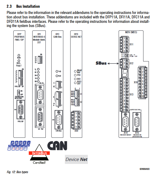
Corresponding bus tabs (PROFIBUS → DFP11A, INTERBUS → DFI11A, etc.) are required, and SBus does not require additional options
Motor adaptation: MDV60A paired with CT/CV (asynchronous servo motor) or DT/DV/D (AC motor with encoder); MDS60A paired with DS/DY (synchronous servo motor)
Project Planning
Software and hardware requirements
Category specific requirements
Software MOVITOOLS package (including bus positioning program), supports Windows 95/98/NT4.0
The frequency converter MDV60A/MDS60A needs to correspond to the bus tab (excluding SBus)
Motor MDV60A: CT/CV (standard encoder), DT/DV/D (optional incremental/combination encoder); MDS60A: DS/DY (standard rotary transformer)
Encoder mechanical connection locking: no need for external encoder; Non locking: requires external incremental (connected to X14) or absolute encoder (connected to DIP11A tab X62)
core functionality
Positioning capability: Supports custom target location, with maximum travel depending on the unit (1/10mm → 3.27m, mm → 32.7m, cm → 327m)
Operation mode: 3 types (manual mode, reference mode, automatic mode)
Auxiliary functions: software limit switch, reference offset adjustment for mechanical zero point, bus data loop interaction (set value/actual value)
Key configurations
Drive scaling: The encoder pulse/stroke unit ratio needs to be set, and it can be automatically calculated without an external encoder (input drive wheel diameter/screw pitch, gear ratio)
Limit and reference: The software limit should be within the hardware limit range, and the reference cam should not overlap with the software limit (otherwise trigger F78 fault)
Installation configuration
software installation
Step operation content
1. Insert the MOVITOOLS CD and run “{CD drive letter}: setup” to install the main program
Insert the bus positioning floppy disk and run “{floppy drive letter}: setup” to install the supplementary program
3. Start MOVITOOLS and select the PC COM port to establish a point-to-point connection with the frequency converter
Hardware wiring
Basic unit wiring: Controller enable (DI ØØ), emergency stop (DI Ø 1), reference cam (DI Ø 3), limit switch (DI Ø 4/CW, DI Ø 5/CCW), encoder (X15/motor encoder, X14/external incremental encoder) need to be connected
Bus wiring specifications (core parameters):
table
Bus type, maximum number of nodes, maximum cable length, baud rate options tab, model
SBus 64 125kbaud → 320m, 1000kbaud → 40m 125/250/500/1000 kbaud None (standard)
PROFIBUS – – 9.6k-1500 kbaud DFP11A(8227241)
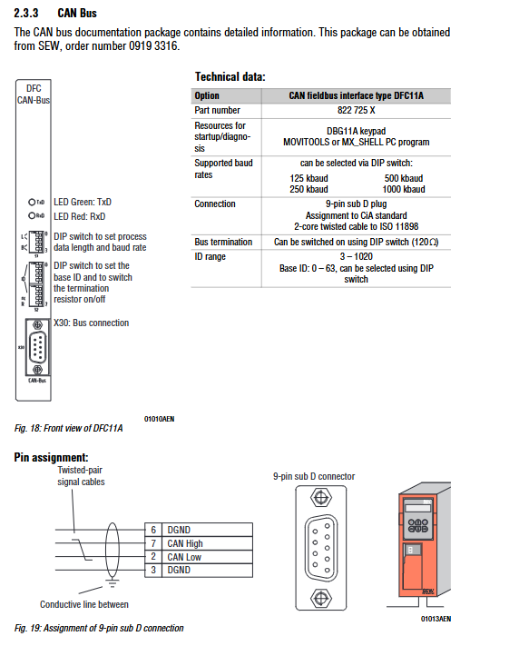
CAN Bus – – 125/250/500/1000 kbaud DFC11A(822725X)
DeviceNet 64 – 125/250/500 kbaud DFD11A(8228876)
Limit switch: NC contact (low level effective) is required, and the cam needs to cover to the end of the travel
Start the process
preliminary preparation
Connect the frequency converter to the PC (RS-232, via USS21A tab)
Start MOVITOOLS → Shell and set the frequency converter to the corresponding operating mode:
MDV60A+DT/DV/D: VFC-n-CON mode
MDV60A+CT/CV: CFC mode
MDS60A+DS/DY: SERVO mode
External encoder configuration: Absolute encoder needs to first activate DIP11A tab; Incremental encoder needs to set P942-P944 (encoder coefficient/scaling) in Shell
Core startup steps
Step operation content
1. Start the “Start/bus positioning” program in the shell
2. Set bus parameters: select bus type, address, timeout time (0.01-650s), timeout response (such as quick stop), baud rate
3. Set scaling parameters: Select the position source (motor encoder/external encoder), and when there is no external encoder, input the drive wheel diameter/gear ratio to automatically calculate the scaling factor
4. Set slope and limit: Enter software limit (user unit), reference offset, reference operation type (0-7 types), slope time (manual/automatic mode, unit s), maximum speed (automatic/manual mode needs to be 10% smaller than P302)
5 Download Program: Click<Download>to download the parameters and IPOS program to the inverter, and optionally switch to monitoring mode
Start operation mode
Reference mode (establishing mechanical zero point):
PO1 control word bit11=0, bit12=1, DI ØØØ/DI Ø 1 set to “1”
PO1 bit8=1 starts the reference operation, and the drive continues to run after reaching the reference cam (DI Ø 3=1). When leaving (DI Ø 3=0), the positioning stops
PI1 bit2=1 indicates reference completion, mechanical zero point=reference position+reference offset
Manual mode (jog operation):
PO1 control word bit11=1, bit12=0
PO1 bit9=1 (Jog+)/bit10=1 (Jog -) controls direction, PO2 sets speed
Automatic mode (precise positioning):
Reference operation needs to be completed first, PO1 control word bit11=1, bit12=1
PO2 sets speed, PO3 sets target position, PO1 bit8=1 starts positioning
PI1 bit3=1 indicates arrival at the target location and supports continuous updating of the target location
Operation and maintenance
Fault handling
Fault storage: P080 fault memory records the last 5 faults, including operating status, current, temperature and other information
Reset method: Power off restart (required ≥ 10s), DI02 terminal reset, MOVITOOLS manual reset, DBG11A button reset
Common faults and solutions:
Fault code, fault name, handling measures
F27 limit switch missing check limit switch wiring, short circuit corresponding terminal when not in use
F39 reference operation fault check reference cam wiring, reference operation type setting
F78 IPOS software limit adjustment software limit position to ensure that it does not exceed the hardware limit
F28 bus timeout check bus connection, extend timeout time (P819)
Key automatic setting parameters
Automatically configure the following parameters after startup and prohibit modification:
Parameter number, parameter name, set value
P100 setting value source SBus or FILDBus
P101 control signal source SBus or FILDBus
P302 maximum speed 1 0-5500 rpm
P600-P604 binary input DI01-DI05 enable/emergency stop, reset, reference cam, CW limit, CCW limit
P813 SBus Address 0-63
P816 SBus baud rate 125/250/500/1000 kbaud