SEW EURODRIVE’s MOVIDRIVE ® Series frequency converter UL certification related technical data sheet
Overview
Name: MOVIDRIVE ® MDX60B/61B/62B, MDR60A/61B, compact, A – Information regarding UL
Core positioning: A technical data sheet designed specifically for UL certification compliance, focusing on key requirements for frequency converter installation, wiring, and protection configuration. It is accompanied by detailed wiring diagrams to ensure that the product complies with the National Electrical Code (NEC) and local additional specifications
Applicable voltage levels: 230V (200-240V), 400-500V (380-500V)
General restrictions:
UL certification is not applicable to non grounded star point power supply systems (IT systems)
The external 24V DC power supply must meet the following requirements: maximum voltage ≤ 30VDC, maximum current ≤ 8A
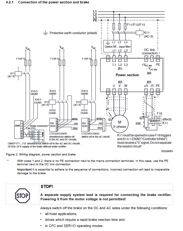
Braking system: For elevator applications, rapid braking response requirements, and in CFC/SERVO mode, both the AC and DC sides of the brake must be simultaneously disconnected
General technical requirements (common to 5 series)
Power Terminal Wiring Specification
Specific description of the required type
The wire material only allows the use of copper wires
Temperature rating – low-power models (such as MDX60B/61B 0005-0300, compact 0015-0300): 60/75 ℃
-High power models (such as MDX60B/61B 0370-2500, compact 0370-0750): 75 ℃
Tightening torque divided by model size (Nm):
– Size 0S/1/2S:0.6
– Size 2:1.5
– Size 3:3.5
– Size 4/5:14
– Size 7:70
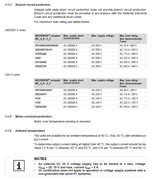
Short circuit current rating (SCCR)
Core specifications:
Fuse/circuit breaker protection: maximum 200000 rms symmetrical ampere (200 kA), voltage ≤ 500V
ABB/Rockwell Type E combination motor controller protection: maximum 65000 rms symmetrical ampere (65 kA), voltage 460-480V
Special note: The SCCR rating of MDR60A/61B (regenerative power unit) is consistent with the matching frequency converter
Environmental temperature and output current derating
Temperature Range Capacity Reduction Rules Applicable Series
40-50 ℃ 2.5%/℃ MDX60B/61B, MDX62B, compact, A series
50-60 ℃ 3%/℃ MDX60B/61B, MDX62B, compact, A series
40-60℃ 3%/℃ MDR60A0150-0750
Basic conditions: No capacity reduction below 40 ℃, maximum applicable temperature is 60 ℃
Exclusive technical requirements for each series
MDX60B/61B series
Model range: 0005-2500 (400-500V), 0015-0300 (230V)
Size coverage: Size 0S, 0M, 1, 2S, 2, 3, 4, 5, 6, 7
Branch circuit protection selection (example: 400-500V):
Model: Non semiconductor fuse (maximum), reverse time circuit breaker (maximum), Type E combination motor controller (ABB)
0005(Size 0S) 15A/600V 25A/500V MS132-2.5(480V,1HP)
0150(Size 3) 175A/600V 90A/500V MS450-40E(480V,30HP)
2500(Size 7) 600A/600V 600A/500V –
Motor overload protection: Comes with load/speed sensitive protection, trip current=150% of rated motor current, supports thermal memory after power failure
MDR60A/61B+MDX62B series
MDR60A/61B: Regenerative power supply unit, models 0150-0750 (MDR60A), 1600-2500 (MDR61B), only 400-500V
MDX62B: Model 1600-2500, only 400-500V, Size 7
Core difference: MDR series needs to be compared with MOVIDRIVE ® The frequency converter is used in conjunction with the system, and the SCCR rating is determined by the frequency converter
Compact series
Model range: 0015-0750 (400-500V), 0015-0300 (230V)
Size coverage: Size 1-5
Branch circuit protection: Only non semiconductor fuses are specified. The maximum fuse current for 400-500V models is 500A/600V, and for 230V models it is 350A/250V
Special requirement: Additional motor overheating detection function is required
A series
Model range: 0015-0750 (400-500V), 0015-0300 (230V)
Size coverage: Size 1-5
Branch circuit protection: Consistent with the compact series, the maximum fuse current for 400-500V models is 500A/600V
Special requirement: Additional motor overheating detection function is required
Key wiring configuration
Classification of Core Wiring Diagrams
Key rules for wiring type coverage content
Power supply section+brake L1/L2/L3 connection, PE grounding, brake AC/DC side cut-off. The brake rectifier needs to be independently powered, and motor voltage supply is prohibited
DC link connection between MDR series and inverter DC link anti reverse connection to avoid equipment damage
When the brake resistors (BW series) BW…, BW… – T (built-in temperature switch), BW… – P (auxiliary contact) trigger protection, the K11 contactor needs to be disconnected without interrupting the resistance circuit
Key points for wiring safety
Size 1/2/2S models: The power terminal (X1) and motor terminal (X2) do not have PE interfaces and require the use of PE terminals next to the DC link (X4)
Brake connector: Strictly follow the wiring sequence, incorrect connections can cause irreversible damage to the brake
Wiring of brake rectifier: When installing in the control cabinet, the connecting wire should be separated from other power cables and only allowed to follow the same path as the shielded power cable