SEW MOVIDYN ® Series servo controller
Overview
Name: MOVIDYN ® Servo Controllers Operating Instructions
Core purpose: To guide the safe installation, start-up, operation, and maintenance of this series of servo controllers, suitable for driving permanent magnet synchronous servo motors in industrial and commercial systems (requiring adaptation to frequency converters)
Prohibited use scenarios:
Explosion-proof area
Exposure to harmful oils, acids, gases, dust, radiation, and other environments
Non fixed applications with mechanical vibrations and impacts exceeding the requirements of EN 50178
Undertaking equipment and personnel safety functions without a high-level security system
Safety and Equipment Fundamentals
Security level and consequences
Possible consequences of hazardous types
Serious electrical hazards or fatal injuries
Immediate danger, serious or fatal injury
Minor injury in dangerous scenarios
Harmful scenario equipment or environmental damage
Equipment classification and identification
Product Series:
MPR/MPB: Power module (MPB includes brake chopper, MPR is regenerative power unit)
MAS: Axis Module (Independent Axis Control)
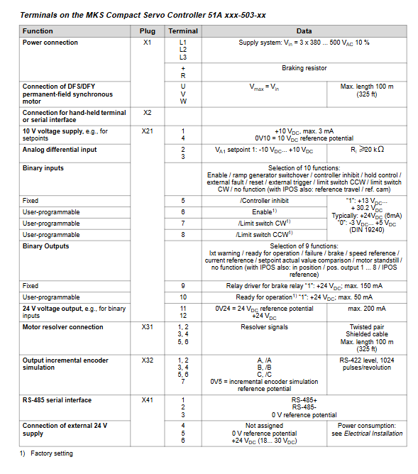
MKS: Compact servo controller (integrated power and axis control functions)
Model interpretation: including information on rated current/power, voltage, design type, etc. (such as MAS51A005-503-00:5A, 380-500V, standard design)
Standard accessories:
Shielding clip (used for motor/braking resistor/signal cable shielding connection)
Tab slot (supporting AIO11/AFC11 and other functional extensions)
Status LED (3 LEDs for power module, 7-segment code display for shaft module/compact controller)
Installation requirements
Basic installation parameters
Specific standards for required types
Tightening torque MKS: 1.5 Nm; MPB/MPR/MAS:3.5 Nm
Installation spacing at top/bottom ≥ 100mm; multiple heat sinks need to be connected with bridging components
The installation posture is only vertical, and the module needs to be completely fixed on a single heat sink
The cable requirement is that the motor cable should be up to 100m long, and the resolver cable should be up to 100m long (0.25mm ² for ≤ 50m, 0.5mm ² for>50m)
Wiring and Protection
Grounding requirements: The PE conductor should have the same cross-section as the power line, and the module casing should be in metal contact with the switchgear mounting plate for grounding
Bus connection:
RS-485: Up to 32 units, cable length ≤ 200m, requires twisted pair shielded cable+0V5 reference potential line
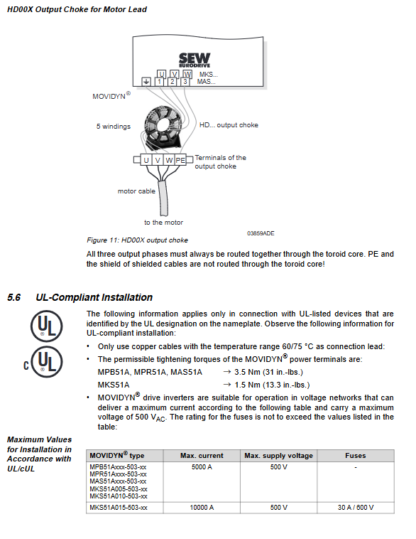
EMC protection: NF series filters are required on the input side, and HD series reactors or shielded motor cables are required on the output side; Control cables and power cables are routed in separate slots, with both ends of the shielding layer grounded
UL Compliance Requirements
Cable specification: Only use 60/75 ℃ copper cable
Fuse selection: Suitable according to module type, maximum voltage 500VAC, current 30-10000AAC
Tightening torque: MKS is 1.5 Nm, other modules are 3.5 Nm
Start the process
Starting premise
Complete installation inspection, disconnect X21 terminal to prevent accidental motor start-up
Axis address setting: Set through the S1 button (0-59), multi axis systems need to avoid duplicate addresses
Initiate core steps
Step operation content
1. Connect PC to controller (MPB/MPR via RS-232, MKS via USS21A options)
Install and start the MD_SHELL software, configure the PC interface (COM port) and controller address
3. Enter motor parameters (model, rated voltage/speed/current, braking type, etc.)
4. Configure controller parameters (damping coefficient 0.5-2.0, stiffness coefficient 0.5-2.0, etc.)
5 programming terminal functions (binary input/output allocation, such as limit switches, brake control)
6. Transfer parameters to the controller and optimize control parameters through MD_SCOPE (optional)
Key Settings
Braking control: External relays/contactors need to be controlled through X21.9 terminals, and direct driving of braking is prohibited (maximum 150mA)
Limit switch: When not connected, X21.7/X21.8 should be short circuited to+24V, otherwise F27 fault will be triggered
Operation and maintenance
Operation display
Power module LED:
ON (green): ready; 24V (green): 24V power supply is normal; TRIP (red): Fault
7-segment code display: contains 16 states (such as “1”=speed control enabled, “F”=fault flashing, “b”=not ready)
Fault handling
Fault storage: Record fault codes and the operating status at the time of triggering (current, speed, etc.)
Reset method:
Power off and restart (waiting for ≥ 10 minutes)
Manual reset (P632, via terminal or software)
Automatic reset (P630, up to 5 times, restart time 3-30s)
Common faults and solutions:
Fault code description and handling measures
F01 overcurrent check motor/cable short circuit, replace module if damaged
F07 DC bus overvoltage extension deceleration ramp, check the brake resistor wiring
F14 Resolver fault check Resolver cable connection and shielding
F27 limit switch cable missing inspection limit switch wiring, if not in use, short-circuit the terminal
Parameter Settings
Core parameter category:
Set value/slope: speed range -5000~5000 rpm, slope time 0.00~30s
Controller parameters: Speed controller gain (0.10-32.00), time constant (0-300ms)
Monitoring function: speed monitoring (P510), current reference value (P410)
Special functions: Factory reset (P610), parameter locking (P640)
Technical data
General Parameters
Working temperature: 0-45 ℃ (without capacity reduction), with a capacity reduction of 3% for every 1K increase in temperature between 45-60 ℃
Storage temperature: -25~70 ℃
Protection level: IP20 (EN 60529)
Installation height: ≤ 1000m (over 1000m, capacity reduction of 1% per 100m)
Core module technical data (example)
Module type Rated power Rated current Weight (kg) Size (W × H × D, mm)
MAS51A005 – 5 AAC 3.5 70×380×250
MPB51A011 11 kW 16 AAC 5.5 105×380×250
MKS51A015 – 15 AAC 6.5 130×336×325