Smiths connectors MHD/MDD/MDP series high-density PCB connectors
Smiths Connectors’ MHD/MDD/MDP series high-density PCB connector product catalog adopts Hypertac hyperbolic contact technology, which has core characteristics such as low insertion and extraction force, 100000 long contact life, low contact resistance, high current rating, and shock vibration resistance, bringing advantages such as high-density interconnection, low holding cost, and low power consumption; The document provides a detailed list of technical parameters, ordering rules, module configurations, plug-in tolerances, termination methods, dimensional specifications, guiding devices, and circuit board preparation details for the MHD, MDD, and MDP series. It also introduces the compatible power/high-frequency contacts and extraction tools, while marking the universal materials, environmental, and electrical characteristics of the entire series, as well as Smiths Connectors’ global support channels. The products are suitable for harsh environments and have outstanding reliability and safety.
Core technology: Hypertac hyperbolic contact technology
This technology is the core competitiveness of connectors, designed for high reliability and high safety applications in harsh environments. The contact sleeve is composed of contact wires arranged in a double curved surface, forming multiple linear contact paths with the pins. The core features and advantages are as follows:
Core Features
Low insertion and extraction force: precise control of pin insertion and extraction force through contact wire angle, smooth deflection of spring wire and contact with pin wire
Long contact life: Smooth and gentle wiping action reduces contact surface wear, supports ≤ 100000 insertion and extraction cycles, with minimal performance degradation
Low contact resistance: The contact area is larger, and the erasing action ensures a clean contact surface. The resistance is about 1/2 of traditional design
High current rating: customizable number, diameter, and angle of contact wires, amplifying current carrying capacity by increasing the number of wires
Anti impact vibration: The contact wire is lightweight and has low inertia, and can follow the intense displacement of the pins. It has 360 ° full circle contact and three-dimensional symmetry, ensuring electrical connectivity in all scenarios
Core strengths
High density interconnect system: significantly reduces the size and weight of subsystems, eliminating the need for additional hardware to overcome plugging and unplugging forces
Low holding cost: Performance far exceeds most product requirements, avoiding the cost and burden of replacing connectors/entire subsystems
Low power consumption: Low contact resistance reduces the voltage drop of the connector, reducing system power consumption and heat generation
Ultimate contact performance: reduces heat accumulation, small volume contact components can carry larger currents, and there is no negative impact of high temperature
High reliability in harsh environments: maintains electrical integrity under extreme conditions such as impact and vibration, with no risk of failure
General Technical Specification (MHD/MDD/MDP series universal)
The three major series adopt a unified core material, coating, environment, and electrical characteristics, with key parameters marked in millimeters. Special contacts comply with the NFC 93569 standard, as shown in the table below:
Category specific parameters, key numbers/standards
Material and coating insulator: Dially Phtalate UL94vo; Frame: Aluminum alloy; Contact: Copper alloy; Guiding components: brass+nickel/stainless steel; Contact plating: Ni+Au UL94vo, Ni+Au
Environmental characteristics temperature range; Contact anti pull safety distance (static/dynamic); Insertion and extraction cycle; Pull out force; Special contact standard -55 ℃~+125 ℃; 2mm/1.80mm; 5000 times; ≤0.5N;NFC 93569
Electrical characteristics – Contact resistance (signal/power); Current rating (signal/power); Insulation resistance; Voltage rated value; Voltage resistance; Contact diameter (signal/power); Coaxial impedance ≤ 12m Ω/≤ 2m Ω; 3A/15A; >10⁴MΩ;200V;800V; 0.50mm/2.00mm; 50Ω
Detailed specifications of the three major product series
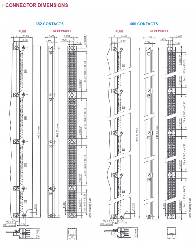
The three major series are all designed around high-density PCB connections. MHD is the main series with full specifications (52-400 contacts), while MDD/MDP is the simplified specification series (MDD: 100/200 contacts); MDP: 200 contact points), each series includes seven core modules: ordering rules, module configuration, standard plugging and unplugging stages, termination methods, connector dimensions, guiding devices, and circuit board preparation details. The core differences and key information are as follows:
MHD series
Module configuration: Supports single channel (26/50 channels), mixed channel (including 4 special contacts), with contact specifications such as 052/100/152/200/252/300/352/400
Standard insertion and extraction stage: Acceptable vertical misalignment * * ≤ 1mm * *, horizontal misalignment * * ≤ 0.70mm * *, tilt * * ± 3 ° * *, minimum gap after insertion is 0.30mm, maximum displacement during insertion and extraction is 0.15mm
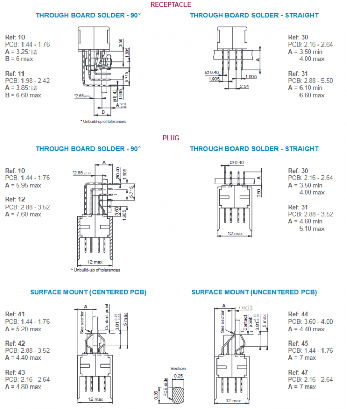
End connection method: including 90 ° through-hole soldering, straight through-hole soldering, surface mount (center/non center PCB), suitable for PCB thickness of 1.60-3.80mm
Connector size: The plugs/sockets with 52-400 contacts are labeled with detailed dimensions, and the fixing screws are M2 x 5, including theoretical dimension labeling
Guidance device: separate plug/socket guidance, including polarized/non polarized, vertical/horizontal installation, grounding type, etc., torque 25N.cm/15N.cm, single set weight 0.55~1.50gr
Circuit board preparation: available in 52/5HA/100/1HB configurations, with clear drilling dimensions (minimum Ø 0.55/Ø 0.80), hole layout, and compatible guide component models
Supporting contacts: Provide power contacts (90 °/straight/welded barrel end connections, including corresponding P/N), high-frequency contacts (compatible with flexible/semi-rigid cables, including coaxial 50 Ω), and extraction tool P/N: SD-03000CX003
MDD series
Module configuration: Only supports single channel, including 50/100/200 channel modules, with socket terminal side view as the core reference
Standard insertion and extraction stage: completely consistent with MHD, with no difference in misalignment, tilt, clearance, or displacement tolerances
Termination method: The basic termination method is the same as MHD, and a new straight through-hole soldering is added to adapt to 4.50mm PCB (Ref: 96)
Connector size: Only indicate 100/200 contact specifications, plug fasteners include M2.5 nuts and M2-6 screws
Guidance device/circuit board preparation: Fully reused MHD guidance component model and 100 contact board preparation details, no new specifications added
MDP series
Module configuration: Only supports 200 single channel configurations, which is a minimalist specification series
Standard insertion and extraction stage: follow the universal tolerance standards, consistent with MHD/MDD
End connection method: Retain 90 ° through-hole soldering, straight through-hole soldering, non centered surface mount, suitable for PCB thickness 1.44-4.18mm
Connector size: only 200 contact specifications, plug fixing screw M2.5 (x3), maximum plug size 119mm, socket 111.9mm
Guide device/circuit board preparation: Only label the core guide components (122/134/114/125), board preparation focuses on 200 contacts, and specifies the layout of 200 minimum Ø 0.55 hole positions
Ordering Rules (General Logic)
The MHD/MDD/MDP series ordering numbers consist of 5 parts: series+layout+components/polarity/coating+termination method+guidance method. The core distinction is:
Components/Polarities/Coatings: Male plugs (standard plated/pre tinned), female sockets (standard plated/pre tinned), MDD/MDP adds MIL coating/tin plating specifications
Termination method: 90 °/straight soldering and SMT mounting corresponding to different PCB thicknesses using digital encoding
Guidance method: Digital encoding corresponding to polarized/non polarized, vertical/horizontal, grounding/power type guidance components